Homebuilt 100A DC welder

   / Homebuilt 100A DC welder #1  

Aussiebushman

Gold Member
Joined
Jul 31, 2008
Messages
252
Location
Jerrong, south of Oberon in NSW, Australia
Tractor
Ford 6000
Ok all you "build-your-own" experts - where have I screwed up?

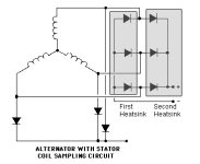
A Marelli (Lucas) 100A alternator was given to a mate (formerly a highly skilled marine electrician) to remove the internal regulator and make up the connections so the field would be activated by a 12V car battery, but the output would be unregulated DC. He seems to have removed the diodes and regulator- see picture.

The basic schematic was the one on the Internet for a Chrysler 120A unit. Power comes from a 5.5Hp 4 stroke petrol engine. The control box contains the wiring from the field via a fuse and switch to the battery. The switch is adouble pole, double throw unit wher one side has a 1 Ohm resistor, the other no resistor. I should actually prefer a rheostat to vary the field and thus the welder amps. The hot wire from the alternator goes though a shunt/meter connection. The negative comes from the alternator frame and there is a Voltmeter across the welding terminals.

First try, there was a pathetic spark at the welding tip. It seemed though the regulator has not been removed. An Ohm-meter reads that one brush is connected directly to the main + terminal with the other brush grounded.

My worry is that if the alternator wiring is wrong, it may dump 100A into the 12V Lead acid battery with potentially disasterous results, even though in theory the fuse would blow.

Where should each of the wires from the brushes go?
Does it appear that the internal rectifier has been eliminated in error?
If so, can I reuse any of the connections that were cut to add an external rectifier and if so, what is recommended?
Alternatively, should I place my head between my knees and kiss my arse goodbye>

Two local auto electricians have virtually refused to help, but I figure someone on this forum can advise - any thoughts appreciated.

Cheers

Alan
 

Attachments

  • Al's DC welder (600 x 506).jpg
    Al's DC welder (600 x 506).jpg
    134.1 KB · Views: 3,073
  • Wrong wiring of regulator.jpg
    Wrong wiring of regulator.jpg
    87.5 KB · Views: 1,962
  • alternator welder schematic.jpg
    alternator welder schematic.jpg
    43.7 KB · Views: 9,702
   / Homebuilt 100A DC welder #2  
This is just my .02 but I am worried for you if something goes wrong with this homemade welder, I would rather spend some money and buy a unit that is UL certified and that you know isnt going to blow up in your face. Im not knocking your idea and building abilities I am just concerned.

-Mike
 
   / Homebuilt 100A DC welder #3  
Alan

Lets look at the math here:

5.5hp is 4.1kW. Do I need to tell you that small engine ratings are "optimistic" ? And at MAX RPM of 3600 typically ?

So to be in any way realistic, derate by 25% so that gets us to 3kW. Now I believe you are using a V belt drive to drive that alternator. What is the pulley ratio ? Alternators run easily double engine speed so for your gas engine you would neet at least a 2:1 step up drive.

The V belt is not very efficient, so derate by another 20% now you are at less than 2.5kW. There are reasons why generators are almost exclusively direct drive.

So what was the open circuit voltage when it was running ? Most alternators are 3 phase AC. If you do not have the diodes in place, it will be completely useless to you for welding. If you simply short the 3 stator windings together it will never work and it will be toast pretty soon.

Looking at this website Alternator Secrets
you should understand how they work, and avoid generating such a high voltage that you kill yourself ! The article says a regular automotive alternator can generate over 120 volt.

Here is a schematic of a typical alternator: (not showing the diodes)
alt_02_1.gif


Theoretically, at to dissipate 2.6kw @ 100 amps with no lead resistance (at the terminals of the alternator) the output voltage would have to be 25 volts while under load. This would mean a substantially higher open circuit voltage. So if you don't see at least 40 volts open circuit, you are not cranking it fast enough or the field current is too low. Or the alternator is a dud and your friend screwed it up...

Let us know how it goes..
 
   / Homebuilt 100A DC welder
  • Thread Starter
#4  
Thanks guys - please take the following as comments on the "work in progress"

Mike's comment is understandable and correct, but I'm located on a remote property with power coming from a 6.5 KVA generator (plus solar/wind battery 2V DC) so it is not quite as simple as buying some stock unit. I already have a 120 Amp AC stick welder that works OK but there is insufficient grunt to do heavy work. This is the reason I'm experimenting with DC as has been proven for yonks as "weldinators" by the 4WD guys.

Westcliffe's comment are most welcome and accurate. Actually, the drive is a flat serpentine belt but the math will not change much. If necessary, I'll change the driven pulley and/or engine for a larger unit. Alternatively, I could fit the second alternator and control box to my old 3.5 litre Range Rover "bush-basher" OR drive it off the Ford 6000 tractor. It just seemed smarter and more flexible to have the welder mounted on a trolley with its own power source.

The open circuit voltage was only 6 volts and I agree that the field current is the most likely source of the problem - hence my belief that mate John removed more of the internal components, including the diodes than he should heve done. Hence my question - can I wire big external stud diodes into the circuit and if so, where should they connect?

Therse probably seem like stupid questions to an experienced electrician, but I'm just a simple all-round bushie with reasonable skills in most things, but not electronics

Cheers

Alan
 
   / Homebuilt 100A DC welder #5  
You can't connect all three phases together to get more current. It will burn the winding. To make it work you will need three phase to single output transformer (expensive and hard to get the right one) or you need to use internal (sans regulator) or external diodes mounted on a heat sink and forced air cooled. The problem might be that the alternator can't maintain the voltage and the current in the same time. To get 30V at 100A the impedance of the winding has to be about 0.1 ohm. Measure the resistance between center and the phase to get the resistance. The impedance will be higher than that when it is running but can't be lower than resistance. You can mount the diodes on a common heat sink then connect the other end to each diode to one of the phase wires. The heat sink will be one of your welding terminals. The center winding wire will be the other. The polarity will depend on diodes used. The diodes should be rated at least 300V preferably more. Some have plus on the stud and some are reversed. To stabilize the current you might make a coil wound on a piece of iron connected in series with the welding cable. 50mm core diameter, 150 mm long and 250 to 300 turns of 4 mm enamel insulated wire.
I have never built one but a friend of mine made similar welder from a 300A/24V bus alternator. Another guy I used to know built a welder from a dynamo removed from a railroad car. Either welder worked pretty well.
 
Last edited:
   / Homebuilt 100A DC welder #6  
All alternators in cars have the 3 windings feed the output, but through the diodes. DC current is all going the same way, no problem with that.

Alan, you need to be really sure that the windings are connected to the diode pack. I would personally think that the diode pack will be the weak link for this setup when used for welding. If you get 2 heat sinks that you mount isolated from each other (one for the negative leg and the other for the positive leg) and then mount 3 diodes to each it should be a reliable system.

I think the diodes got removed, which will never work. I also think you had better put at least 1 lightbulb (12V 1-5W) in series with the field line so that when you get the diode situation straightened out you don't electrocute yourself by generating 130V. You can later determine the right wattage to get the power to the level you need it. DC is **** on variable resistors for controlling the output, it would be better making a transistorized circuit using 1 power transistor and using one of those 3 legged voltage regulators for a reference voltage. If you want the simplest solution, connect several light bulb sockets in parallel and then in series with the field line. For low power, put in 1 bulb. For more power add a second bulb and so on. Each bulb added lowers the resistance, hence increases the field current

You should be able to rig up a diode tester with your battery and a light bulb in series with one of the lines. Current will flow one way across the diodes but not the other. If you take the diode pack to an auto electrician he should be able to test it and mark the leads so you know how to connect it.
 

Attachments

  • Heat sinks.jpg
    Heat sinks.jpg
    36.4 KB · Views: 2,098
Last edited:
   / Homebuilt 100A DC welder #7  
Search Yahoo Groups for

AmpTramp

Weldernator

hilltopper34w
 
   / Homebuilt 100A DC welder #8  
I was found this on Youtube a few days ago. Read the remarks, and he briefly says what is removed. There are many other homebuilt genwelders on Youtube to get ideas.

YouTube - My Homemade Welder
 
   / Homebuilt 100A DC welder
  • Thread Starter
#9  
My thanks to all of you for the really helpful advice. You are sure to be right that the original diodes got removed. My first challenge is to work out how to rewire the alternator to provide right connections. I know where I can get some big stud diodes at reasonable prices. Then I'll post a schematic incorporating your suggestions to see what you think about it before I do anything stupid.

Thanks and regards

Alan
 

Tractor & Equipment Auctions

2012 FORD F150 XL (A45046)
2012 FORD F150 XL...
2006 V.E ENTERPRISES 130BBL VAC TRAILER (A45046)
2006 V.E...
2018 GMC SIERRA 2500HD (A45046)
2018 GMC SIERRA...
PALLET OF SAFETY FENCE (A45333)
PALLET OF SAFETY...
24ft x 28ft Metal Building (A44391)
24ft x 28ft Metal...
Heavy-Duty 4-Wheel Rolling Warehouse Cart  74in x 32in (A44789)
Heavy-Duty 4-Wheel...
 
Top