nikdfish
Platinum Member
The wife decided she wanted a flagpole up in the front yard by July 4, so I have been working at getting one made. I found a DIY materials list on a flagpole products web site & used it as a basis for ours.
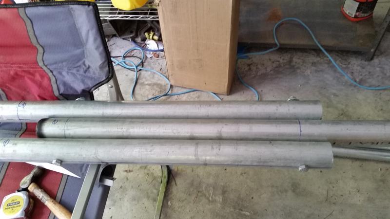
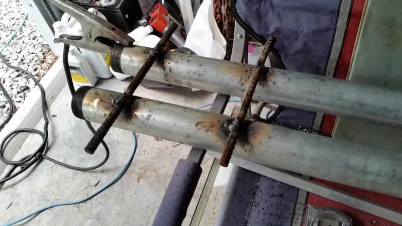
I built a "tip up" version, so it can be lowered if needed for repairs (or whatever), built from 3 ten foot lengths of schedule 40 pipe - 2", 1.5" & 1.25". The base is another 10' piece of 2" that is cut in half & will be set into a concrete base, one leg on each side of the 2" base piece & pinned with a couple of long 1/2" bolts. About 2.5' of the base will be in concrete & the other 2.5' above ground. Rebar was welded to the lower portion of the base to help anchor things in the concrete.
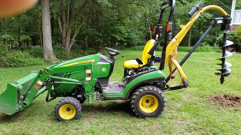
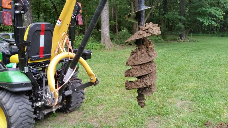
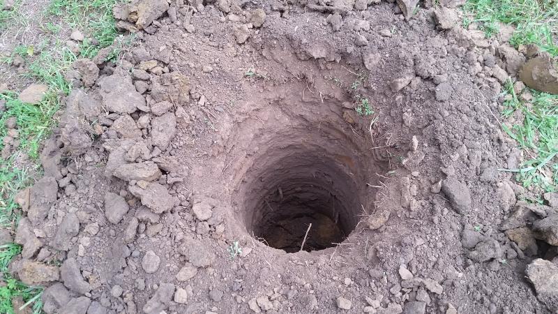
The 3038e was out at the acreage, so I gave the 1025R a try with the PHD and a 12" auger. It was a bit much for the little guy, but I ended up getting a roughly 4' hole sunk for the base.
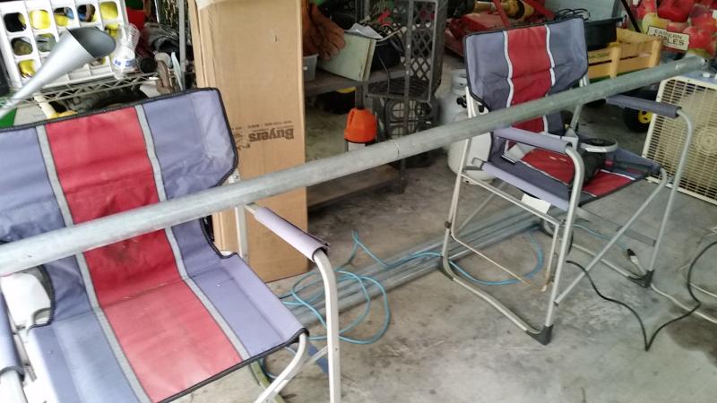
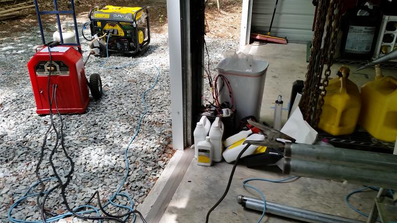
I was working out in the tractor storage building & it is kind of a "make do" setting. Power comes from the generator out there. I spread things out over a few days - the heat & humidity made me disinclined to push too much on any one day.
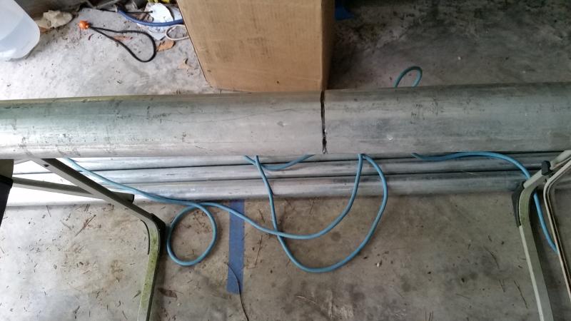
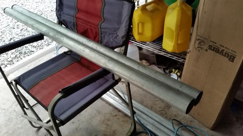
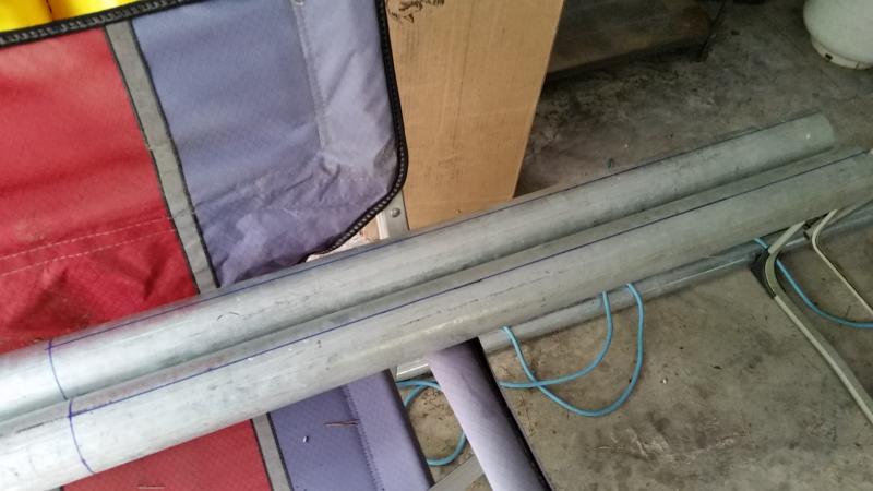
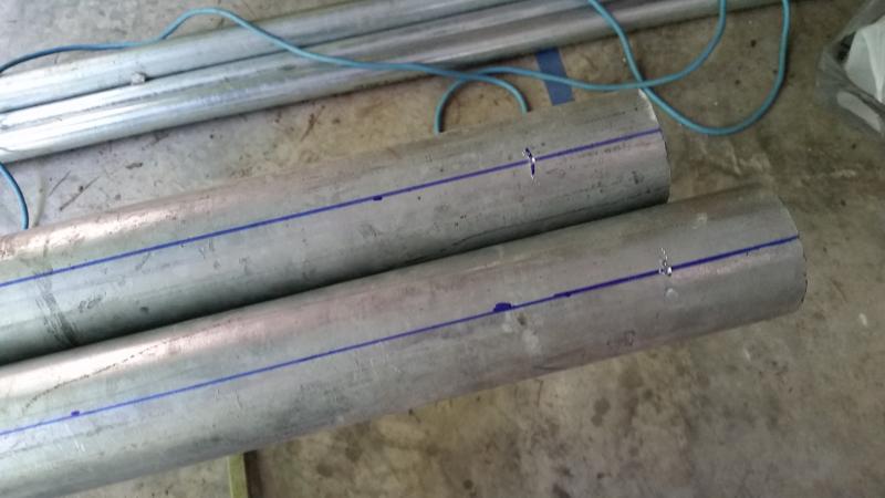
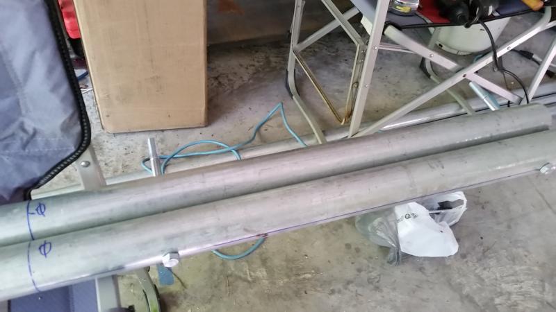
The best way to work with the pipe was a couple of old folding chairs as saw horse stand-ins. First step was cutting a 2" pipe into 2 pieces. The angle grinder was the easiest way to work as the pipe wasn't secured enough for a sawzall. The circumference for the cut was marked using a length of flat ribbon cable from an old disk drive interface as a guide for the marker.
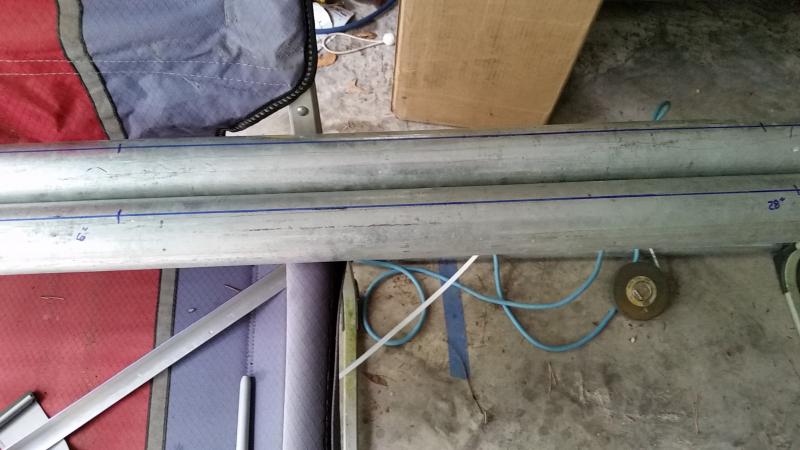
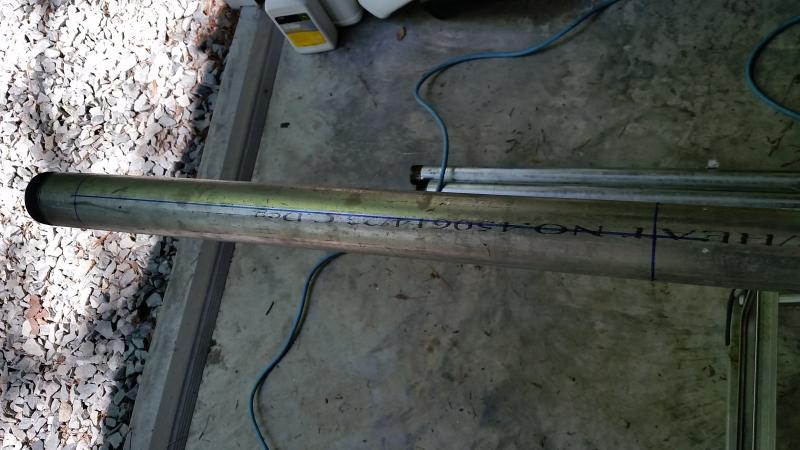
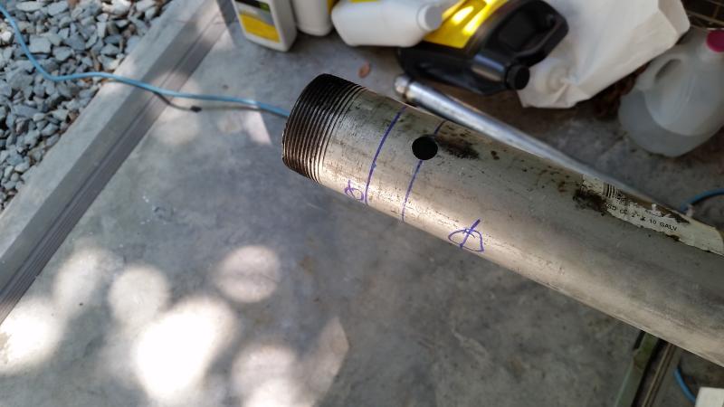
Lines were marked using a piece of angle iron as a self aligning guide & a circumference drawn to mark ground level.
Locations for holes were marked at 6" & 28" up from ground level.
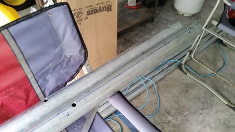
A step drill was used for the first holes
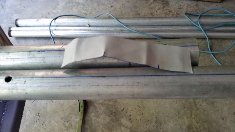
The ribbon cable was used to find the opposite side locations by marking circumference length & marking the halfway point. With the overlap at the original line, the halfway mark set the points for drawing the line on the opposite side.
With the lines drawn, the same measurements from ground level set the punch point for the next holes
With holes drilled, the bolts were used to pin the pieces and verify alignment. A little tweaking of the holes was needed, but not much. The parts were marked to show proper orientation.
The same steps were used to mark corresponding locations on the base of the uncut 2" pipe.
Once the holes were drilled, the long pipe was mated with the base pieces & a small amount of additional tweaking to let the bolts go through easily.
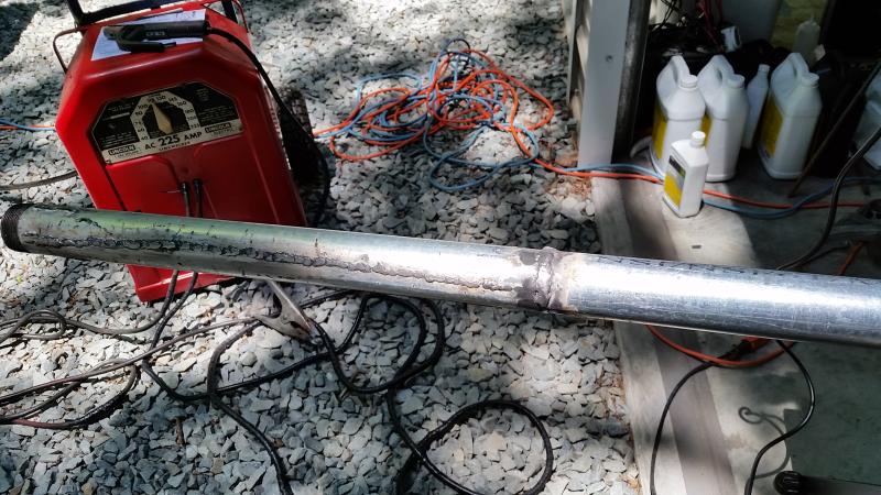
With the pieces in alignment, it was time for adding the plates that will keep the base components in alignment and keep the upright from passing vertical when tipped up. I got out the old Lincoln AC225 & hooked it up to the 7K Champion. I don't claim any skill with the stick welder, this is the second or third project so far & I am learning as I go.
(looking at this last pic, I saw I needed to double check that bottom plate to see if there was interference with the vertical when it gets horizontal ...)
I had a couple of short pieces of 1/2" rebar for the bottom of the base. I need to add a couple of "legs" to extend down to the hole bottom so I can stabilize things at the desired level before adding the concrete.
This is where I quit for the day. The plan was to set the base & concrete it in with the bottom portion (2") of the vertical in place. After the concrete sets, the 2" gets removed & the whole pole assembled. Each joint gets about a 12" overlap. The 1.5" nests easily in the 2" (I may add some beads to tighten the fit some). The 1.25" needed line relieved to clear a ridge on the inside of the 1.5" - and also needed a bit of "whittling" to slide easily (ballpark 0.06" overall).
Getting back to work, I found the lower plate did indeed interfere with the center tube going to horizontal. I had already planned to cut off the visible threaded portions for a cleaner look, so I marked the point where the tube bottom would clear the plate, removed the center tube & cut there as well as the opposite end.
I added a rebar "foot" that should help with getting the base at the proper height & reinforce the concrete plug.
I then reassembled the vertical segment with the base & verified proper range of motion and the ability to re-insert both bolts.
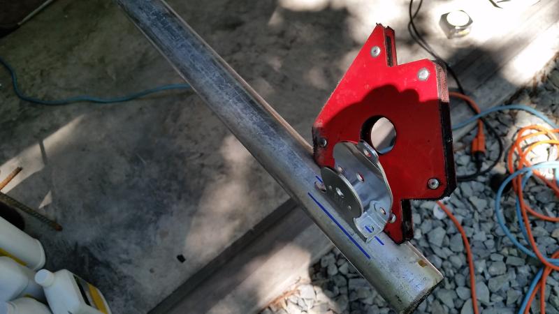
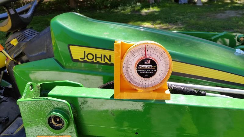
I ordered a dial type level indicator for checking vertical during the install. I wanted to get it right & the degree marked dial indicator gave me more confidence in the results than a bubble level.
I finished mating the top two sections & adding the pulley to the top.
According to nominal specs, it should only have been a matter of about 0.06" removed from the 1-1/4" and relieving a line to get it to nest within the 1-1/2", but it felt like I removed more than that. I was using the angle grinder like a spoke shave to reduce the diameter of about 12" worth of the 1-1/4", starting with a grinding disk & finishing with a flapper.
I used the cut off threaded portion of the 1-1/2" to gauge when it was close enough to try.
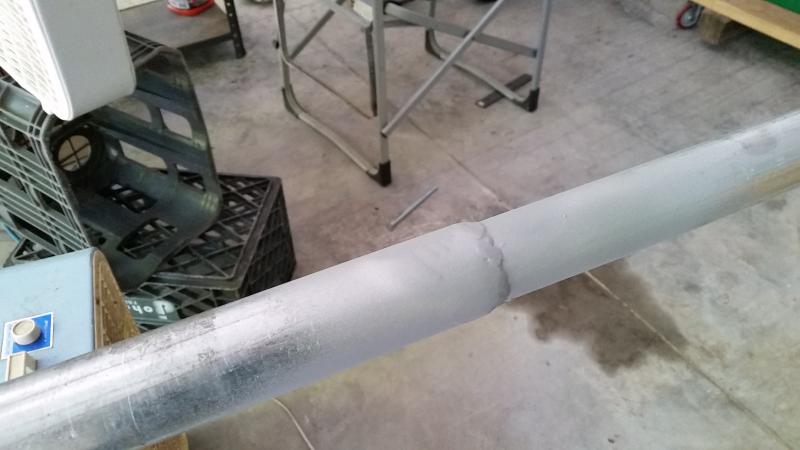
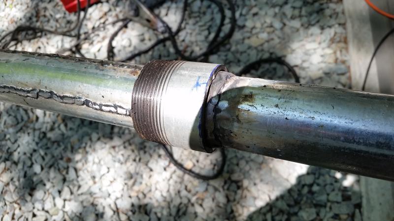
It fit up pretty tight & I was tempted to just leave it there, but in the end decided to run a weld around it to help make up for the reduced wall thickness at the joint.
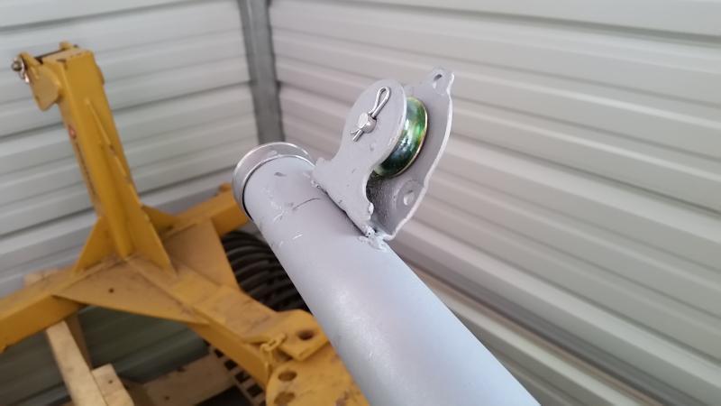
The pulley was disassembled & the framework positioned at the end of the 1-1/4". It got tacks at both ends.
Here after a bit of zinc paint, reassembly and a cap on the end.
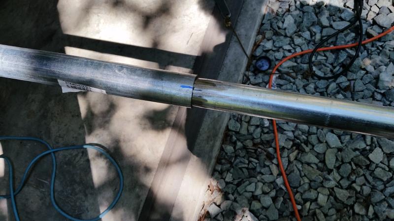
The 1-1/2" fits easily inside the 2", maybe a bit too easily. I decided to put some beads down to reduce the play & help better center it. The cut off portion of the 2" bottom was used as a gauge.
I also ran a bead around the circumference at the joint location, figuring it would be easier to work on the 1-1/2" by itself than juggling it & the 2". The bead stops the 1-1/2" from sliding further into the 2". This got left as-is. I did not feel further welding was really needed & it is a lot easier working with a 19' that just needs to slide in than welding things up and having to deal a 28' piece that has to get lined up for bolting into the base.
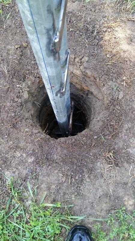
A day or so later, the base got installed in the ground. The hole was pumped out & most of the spoils raked out into the surrounding grass. I dismounted the vertical portion & trial fit the base.
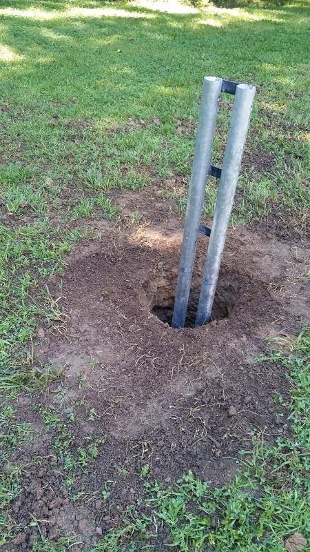
It was about 6" higher than originally planned, but close enough I did not push for deeper. The vertical got re-mounted and readied for bracing. I made a couple of stakes for attaching 2x4's that would sit at right angles around the base. These got C clamped to the vertical. I used the newly arrived dial style angle gauge to check vertical.
I was actually pretty close just eye-balling it. Dead on for one axis & 1 degree off on the other!
With vertical established & bracing done, the concrete got added. I ended up using 6 60 lb. bags to get it up to ground level.
I covered it with some old underlayment & planned to keep it damp for a few days for curing. I decided to a day or two before dropping the vertical to attach the upper portion.
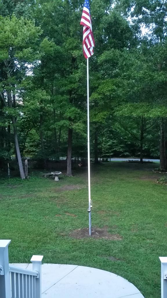
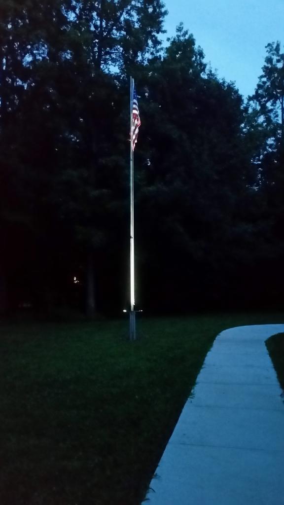
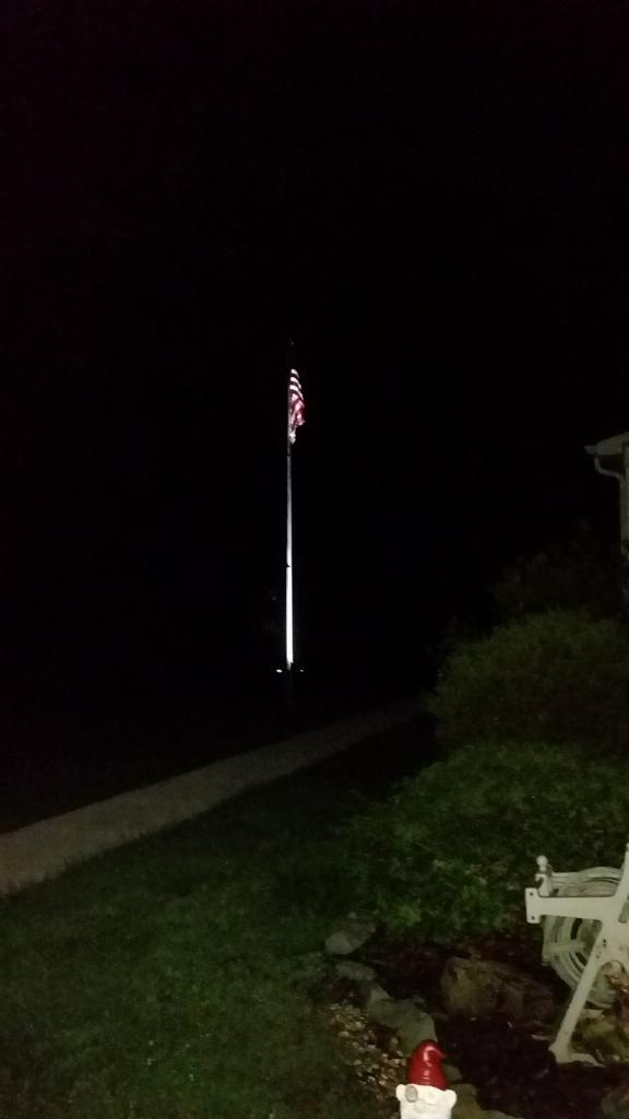
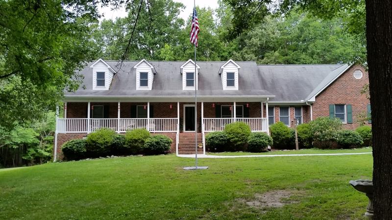
And after a couple more days we are finally done.
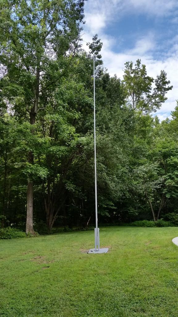
I lowered the vertical to slide in the top section then threaded the haul up line through the pulley & lifted the whole assembly back to vertical.
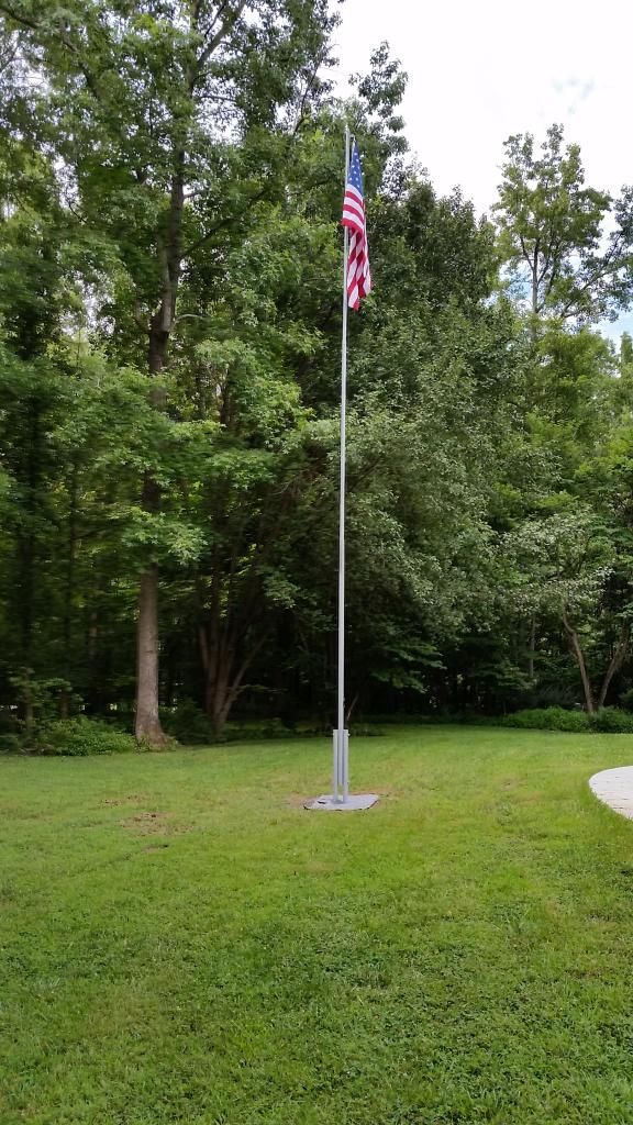
Attached the cleat, adjusted the clips & raised the flag!
All that is left is a bit of landscaping around the base.
(BTW, the flag is a 4'x6' from Annin Flagmakers)
Nick
I built a "tip up" version, so it can be lowered if needed for repairs (or whatever), built from 3 ten foot lengths of schedule 40 pipe - 2", 1.5" & 1.25". The base is another 10' piece of 2" that is cut in half & will be set into a concrete base, one leg on each side of the 2" base piece & pinned with a couple of long 1/2" bolts. About 2.5' of the base will be in concrete & the other 2.5' above ground. Rebar was welded to the lower portion of the base to help anchor things in the concrete.
The 3038e was out at the acreage, so I gave the 1025R a try with the PHD and a 12" auger. It was a bit much for the little guy, but I ended up getting a roughly 4' hole sunk for the base.
I was working out in the tractor storage building & it is kind of a "make do" setting. Power comes from the generator out there. I spread things out over a few days - the heat & humidity made me disinclined to push too much on any one day.
The best way to work with the pipe was a couple of old folding chairs as saw horse stand-ins. First step was cutting a 2" pipe into 2 pieces. The angle grinder was the easiest way to work as the pipe wasn't secured enough for a sawzall. The circumference for the cut was marked using a length of flat ribbon cable from an old disk drive interface as a guide for the marker.
Lines were marked using a piece of angle iron as a self aligning guide & a circumference drawn to mark ground level.
Locations for holes were marked at 6" & 28" up from ground level.
A step drill was used for the first holes
The ribbon cable was used to find the opposite side locations by marking circumference length & marking the halfway point. With the overlap at the original line, the halfway mark set the points for drawing the line on the opposite side.
With the lines drawn, the same measurements from ground level set the punch point for the next holes
With holes drilled, the bolts were used to pin the pieces and verify alignment. A little tweaking of the holes was needed, but not much. The parts were marked to show proper orientation.
The same steps were used to mark corresponding locations on the base of the uncut 2" pipe.
Once the holes were drilled, the long pipe was mated with the base pieces & a small amount of additional tweaking to let the bolts go through easily.
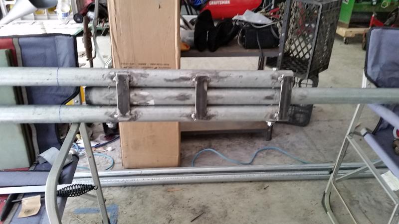
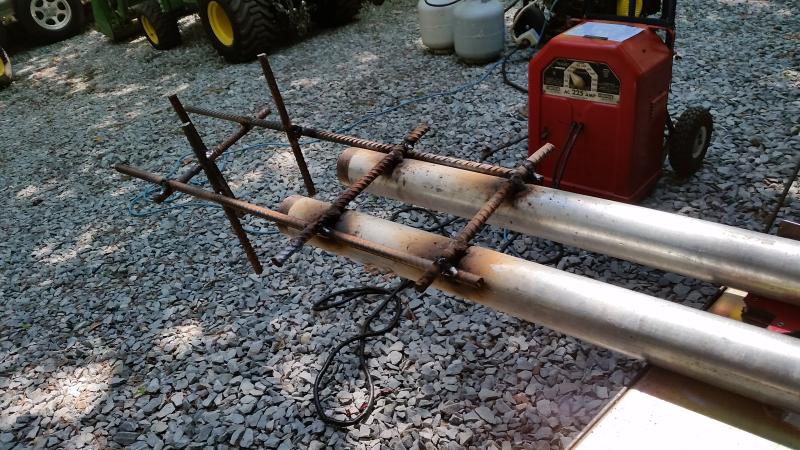
With the pieces in alignment, it was time for adding the plates that will keep the base components in alignment and keep the upright from passing vertical when tipped up. I got out the old Lincoln AC225 & hooked it up to the 7K Champion. I don't claim any skill with the stick welder, this is the second or third project so far & I am learning as I go.
(looking at this last pic, I saw I needed to double check that bottom plate to see if there was interference with the vertical when it gets horizontal ...)
I had a couple of short pieces of 1/2" rebar for the bottom of the base. I need to add a couple of "legs" to extend down to the hole bottom so I can stabilize things at the desired level before adding the concrete.
This is where I quit for the day. The plan was to set the base & concrete it in with the bottom portion (2") of the vertical in place. After the concrete sets, the 2" gets removed & the whole pole assembled. Each joint gets about a 12" overlap. The 1.5" nests easily in the 2" (I may add some beads to tighten the fit some). The 1.25" needed line relieved to clear a ridge on the inside of the 1.5" - and also needed a bit of "whittling" to slide easily (ballpark 0.06" overall).
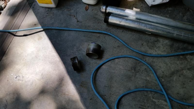
Getting back to work, I found the lower plate did indeed interfere with the center tube going to horizontal. I had already planned to cut off the visible threaded portions for a cleaner look, so I marked the point where the tube bottom would clear the plate, removed the center tube & cut there as well as the opposite end.
I added a rebar "foot" that should help with getting the base at the proper height & reinforce the concrete plug.
I then reassembled the vertical segment with the base & verified proper range of motion and the ability to re-insert both bolts.
I ordered a dial type level indicator for checking vertical during the install. I wanted to get it right & the degree marked dial indicator gave me more confidence in the results than a bubble level.
I finished mating the top two sections & adding the pulley to the top.
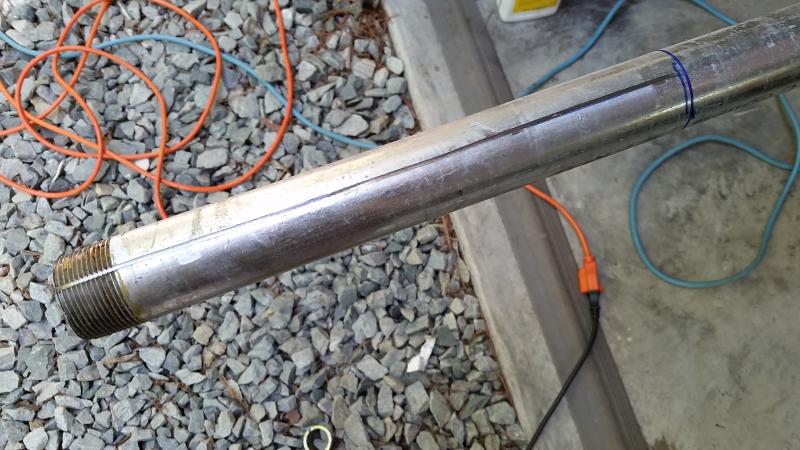
According to nominal specs, it should only have been a matter of about 0.06" removed from the 1-1/4" and relieving a line to get it to nest within the 1-1/2", but it felt like I removed more than that. I was using the angle grinder like a spoke shave to reduce the diameter of about 12" worth of the 1-1/4", starting with a grinding disk & finishing with a flapper.
I used the cut off threaded portion of the 1-1/2" to gauge when it was close enough to try.
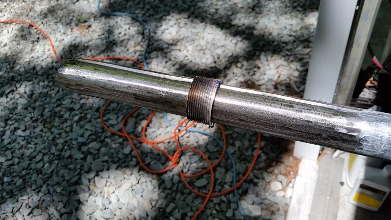
It fit up pretty tight & I was tempted to just leave it there, but in the end decided to run a weld around it to help make up for the reduced wall thickness at the joint.
The pulley was disassembled & the framework positioned at the end of the 1-1/4". It got tacks at both ends.
Here after a bit of zinc paint, reassembly and a cap on the end.
The 1-1/2" fits easily inside the 2", maybe a bit too easily. I decided to put some beads down to reduce the play & help better center it. The cut off portion of the 2" bottom was used as a gauge.
I also ran a bead around the circumference at the joint location, figuring it would be easier to work on the 1-1/2" by itself than juggling it & the 2". The bead stops the 1-1/2" from sliding further into the 2". This got left as-is. I did not feel further welding was really needed & it is a lot easier working with a 19' that just needs to slide in than welding things up and having to deal a 28' piece that has to get lined up for bolting into the base.
A day or so later, the base got installed in the ground. The hole was pumped out & most of the spoils raked out into the surrounding grass. I dismounted the vertical portion & trial fit the base.
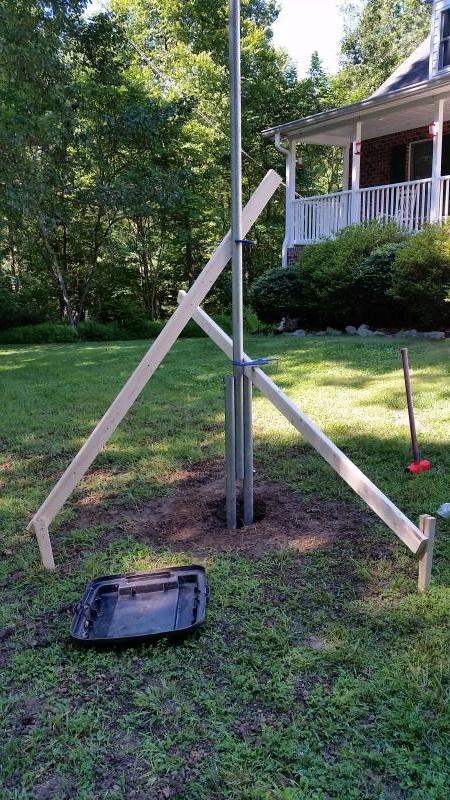
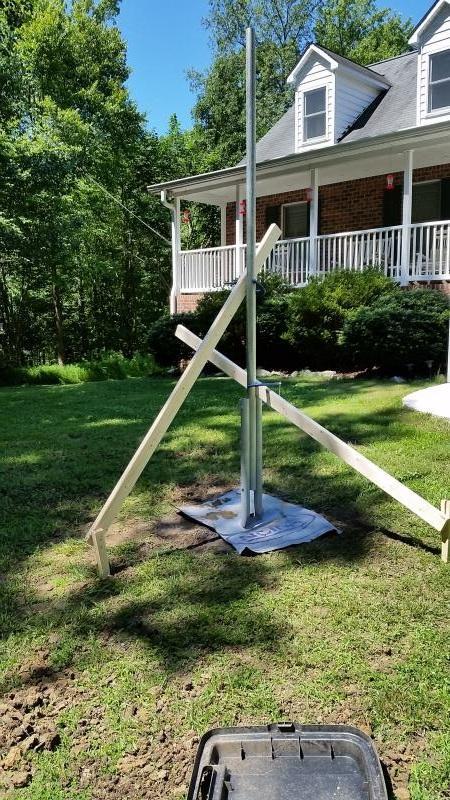
It was about 6" higher than originally planned, but close enough I did not push for deeper. The vertical got re-mounted and readied for bracing. I made a couple of stakes for attaching 2x4's that would sit at right angles around the base. These got C clamped to the vertical. I used the newly arrived dial style angle gauge to check vertical.
I was actually pretty close just eye-balling it. Dead on for one axis & 1 degree off on the other!
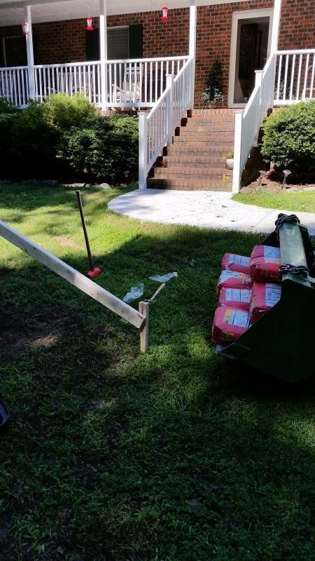
With vertical established & bracing done, the concrete got added. I ended up using 6 60 lb. bags to get it up to ground level.
I covered it with some old underlayment & planned to keep it damp for a few days for curing. I decided to a day or two before dropping the vertical to attach the upper portion.
And after a couple more days we are finally done.
I lowered the vertical to slide in the top section then threaded the haul up line through the pulley & lifted the whole assembly back to vertical.
Attached the cleat, adjusted the clips & raised the flag!
All that is left is a bit of landscaping around the base.
(BTW, the flag is a 4'x6' from Annin Flagmakers)
Nick
")