Dmacleo
Veteran Member
- Joined
- Sep 11, 2020
- Messages
- 1,866
- Location
- Etna, Maine
- Tractor
- 2010 MF GC2400 Owner, 2012 MF1532 User
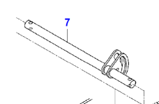
this piece

1:first of all remove the long arm from frame to adjust link both sides, then remove adjust links.
2: remove the pin bolts on both ends of the lift shaft to allow pulling the lift link off. on Left side you will have to pull the 3pt lift arm I just pulled the 2 nuts on end (measured thread distance first for install reference) and loosened the link that way, when lift link off can just rotate and slide off.
Here's where the fun starts. if both will pull off (may have to put vise grips on shaft to hold) them rock link back and forth with hammer if needed. do NOT hammer against the wide portions (eg from under tractor to outside of tractor) as the link WILL bend. if they both come off...GREAT. course my left side stuck on. tried heating with torch, no good, just as my diff lock cable started to burn I ran out of acetylene. Just as well I guess.
This piece:

At that point its sawzall and metal cutting blades. its a *****. have to do a sideways cut from back end towards front and watch for fan interference. A 20V Max dewalt would not handle it, battery overheat. used 7amp corded. broke 5 blades, you will only be using 1 3/4 in of tip of blade with tip 1/8" out at worst point.
but anyways got that off and that side out, took to local garage put the stub end of shaft in vise heated the lift arm and spun it off.
then just remove the bronze bushings on each end.
3: ok that's out of the way. next up pull one bolt on rt side of tractor underneath holding the valve body in place. then pull the 1 bolt to that bracket (most stuff is 12mm thru this) under the floor mat going down. then pull the top bolt on hose end bracket where FEL connections are. this allows moving valve body down and inch and back about 2 inches this allows lift shaft to protrude enough w/o binding on the hyd lines to valve body.
4: pull the frame cross shaft in front of fan, 2 19mm bolts each end. use vise grips on rt side to prevent spinning while remove bolts. I used rt side as it prevented anything from hitting fan. also disconnect any wire looks there and one right where cables come down from engine area. this allows you to above that cross bar fwd about 3 inches and move the lines near fan down a bit to allow the lift limit pawl to clear fan and lines.
5: pull the limit adjust threaded rod out, there is cotter pin below the insert that sits in the shaft pawl.
6: pull front driveshaft (4wd) off rear, I used a wedge inside the split to widen then pry bar to pry off splines.
7: pull shaft out. insert new one. when inserting the limiter needs to face slightly fwd then once past fan rotated back a bit.
8: put everything back together making sure to tie the cables/etc back where fan wont interfere.
I am at step 8 now taking break, figured would post this while fresh in my mind.
cutting that one side took me better part of 3 hours due to blade damage/etc.
Have fun


1:first of all remove the long arm from frame to adjust link both sides, then remove adjust links.
2: remove the pin bolts on both ends of the lift shaft to allow pulling the lift link off. on Left side you will have to pull the 3pt lift arm I just pulled the 2 nuts on end (measured thread distance first for install reference) and loosened the link that way, when lift link off can just rotate and slide off.
Here's where the fun starts. if both will pull off (may have to put vise grips on shaft to hold) them rock link back and forth with hammer if needed. do NOT hammer against the wide portions (eg from under tractor to outside of tractor) as the link WILL bend. if they both come off...GREAT. course my left side stuck on. tried heating with torch, no good, just as my diff lock cable started to burn I ran out of acetylene. Just as well I guess.
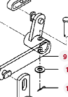
This piece:

At that point its sawzall and metal cutting blades. its a *****. have to do a sideways cut from back end towards front and watch for fan interference. A 20V Max dewalt would not handle it, battery overheat. used 7amp corded. broke 5 blades, you will only be using 1 3/4 in of tip of blade with tip 1/8" out at worst point.
but anyways got that off and that side out, took to local garage put the stub end of shaft in vise heated the lift arm and spun it off.
then just remove the bronze bushings on each end.
3: ok that's out of the way. next up pull one bolt on rt side of tractor underneath holding the valve body in place. then pull the 1 bolt to that bracket (most stuff is 12mm thru this) under the floor mat going down. then pull the top bolt on hose end bracket where FEL connections are. this allows moving valve body down and inch and back about 2 inches this allows lift shaft to protrude enough w/o binding on the hyd lines to valve body.
4: pull the frame cross shaft in front of fan, 2 19mm bolts each end. use vise grips on rt side to prevent spinning while remove bolts. I used rt side as it prevented anything from hitting fan. also disconnect any wire looks there and one right where cables come down from engine area. this allows you to above that cross bar fwd about 3 inches and move the lines near fan down a bit to allow the lift limit pawl to clear fan and lines.
5: pull the limit adjust threaded rod out, there is cotter pin below the insert that sits in the shaft pawl.
6: pull front driveshaft (4wd) off rear, I used a wedge inside the split to widen then pry bar to pry off splines.
7: pull shaft out. insert new one. when inserting the limiter needs to face slightly fwd then once past fan rotated back a bit.
8: put everything back together making sure to tie the cables/etc back where fan wont interfere.
I am at step 8 now taking break, figured would post this while fresh in my mind.
cutting that one side took me better part of 3 hours due to blade damage/etc.
Have fun
Last edited: