MatHaas
Silver Member
Well i'm a newb and a first time tractor owner.
I recently purchased a left over 2016 Mahindra 3550 PST 4wd. I'm budget conservative, so did some searching for a used 75B / Bradco 509 backhoe attachement to go along with the tractor.
What do you know, I come across this used Bradco 509 that came off of a New Holland TN75 at a local used farm equipment lot. I got them down to $3000 cash, a solid score in my book after seeing other prices for used 509s, let alone a new one!
They said it had a few hydraulic leaks but was in good working order. Nothing I was too concerned about, so I went and picked er up.
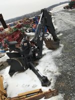
Here is the bradco subrame for the New Holland that came with the hoe
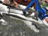
My 3550 has factory subframe braces that tie the loader mount to the rear axle
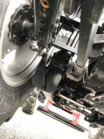
And here is what I wanted to replicate/build; the setup bradco sold for my tractor
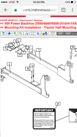
I did some serious research before hand, priced things out, before I decided this was the best route to go. I looked in to buying the subframe from the dealer, but that equated to several thousand dollars (which that cost is usually built in when you purchase the entire 75B setup).
I then looked in to buying the lower rear axle brackets to weld the NewHolland subframe to, so I didn't "destroy" my factory ones, or mess up and be SOL. Well the new axles bracket/plates cost $330 each from the dealer, and that was out the door quick.
So i decided to make my own from scratch. And to cut down the NewHolland subframe to my specs. And weld it all together.
I picked up two 10" x 10" x 0.75" thick plates for the axle plates, and two 12" x 12" x 0.50" thick plates for the 3-point arm brackets and bracing.
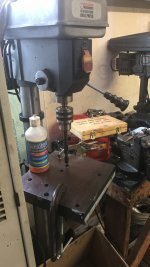
I tacked the 0.75" plates together, tacked the stock plate on top as a template, passed a drill bit down each hole to mark center, ground the tacks off for the stock plate, and went to town drilling these 5/8" holes. Cutting fluid is a must. This Harbor Freight drill press and slow speed drill bits work amazing and is one of the best budget pieces I've bought there. Don't get me wrong, I own Miller welders and other top equipment, but for the price of the HF press, it does one heck of a job for general fabrication. It has minimal run out but that's not critical in these applications.
One they were drilled, I ground off the tacks, traced the stock plate pattern and began to cut. I initally tried using the chinese 50amp plasma cutter we have (brother bought it while we were still in highschool years ago), and that wasn't having it and messed up one of my lines. So after that, I went to town with the dry cut metal chop saw where I could and the angle grinder with cut off wheel where I couldn't get. Man this was an ugly job, lotsssss of grinding. Wish I had a 100amp plasma table, haha (next year!)
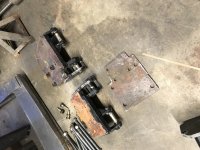
Here you can see I already cut off the axle mount plate on the NewHolland subframe, cut it to the height i calculated, cut the ends off the length I needed (and accidentally measured from the wrong part, cutting on of them too short :laughing: which i had to weld a section back in then), cut a large v groove where the subframe was originally bent but i needed it straight (which i unbent by running it over with the tractors back tires and massage it the rest of the way with the 10lb sledge), and sat the factory plate on top as a mock up for what my plan was. The large bracket/mount that connects to the hoe is 1.25" thick, the rail running up to under the loader is 1" thick by 5". This wasn't fun work, haha, and the first time i've worked with greater than 0.25" for fabrication.
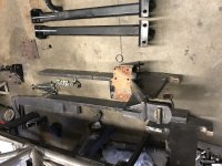
I then made cardboard templates of the 3point link tabs and traced them out to be cut with the plasma (which i found works ok after changing the tip and maxing the air pressure)
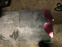
Rough cut straight after the hand plasma action
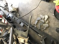
Pin holes drilled and tabs cleaned up, ready for welding
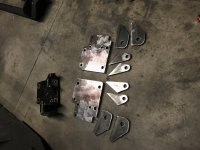
I drew a grid square to the bolt holes with options of where the subframe would weld to and tacked the tabs on
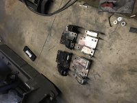
I bolted the new plates ontop of the factory plates to prevent warping during welding and burned them in, with all tabs beveled at the weld joint prior
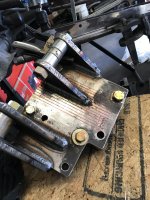
I added on the bracing (some with extra material I had so it wasn't the prettiest) and then used these cool little 90* gussets I have from other chassis fab to keep the plate perfectly square on the subframe rail.
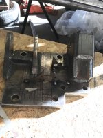
sat er on and tacked it in to place
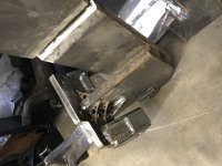
then made the real bracing/gussets
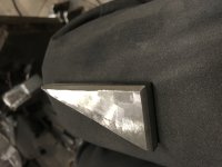
tacked them on, knocked off the small temporary ones, and she was ready
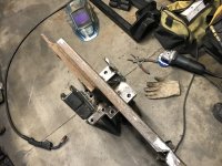
burned er in hot (and in hindsight, probably could have bolted the factor plate on again to prevent warping, but didn't. only had slight warp post cooling which didn't effect fitment)
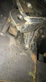
I then needed to fill in the giant notch i made where I removed the bend in the rails. I expected it to warp some, filling in that big with a lot of weld, but thought a few c-clamps and angle iron would do the trick.
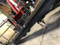
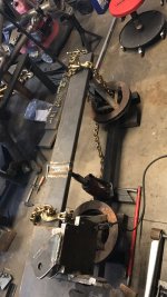
Well after the initial root pass, she was bending on me pretty good and I knew it'd only get worse. So i remembered what a good friend told me to do when welding an axle truss on, chaining the axle on stands to a fab table and using a bottle jack in the center to bend it in the opposite direction. and post welding and cooling, when you relief the pressure, it'll end up straight.
So i rigged up this setup with 1/4" wall 2.5" x 2.5" square tub, inverted F350 superduty rotors that fit my jack stanks, gr70 chains, and a 10 ton bottle jack. Haha. I pretty much maxed the pressure of the jack with the little handle on it, and used an extension to get a little more pressure out of it. It bent the rail back past straight with a slight bow in it. I burned it, let it cool, and to my amazement... it was actually straight!
Next was to tie in the loader frame. Same deal, I cut 5"x7" plates; tacked them together; used the factory brace to pattern the holes and drilled them out. i made these so I could cut a 2" long by 1" high taper out of the rail and have it weld it flush. Gave it a little clearance and smooth transition if I happen to run in to anything. Plus that extra length wasn't really helping me since it was moderately past the frame backing.
Here they are tacked up.
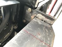
And with that, they were ready for final welding and paint.
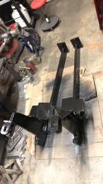
Now, before hand, I measured where the mounts normally come up behind the ROPs, and what that total width was. I then measured the backhoe side mounts and saw what I had to work with to minimize modification. I got lucky, and was able to plan my total tractor mount width to end up 0.25" inside the major plates of the backhoe side mounts. meaning I'd only have to grind the welds off of the stock backhoe side mount points, and flip them to the inside.
And here you can see I did that,
With the one side already removed, and the other side still in "stock" location
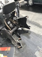
Again, a ton of grueling dirty grinder work.. on heavy material. it just sucks. But i'll make this note, i'm glad the welders bradco employs aren't great ones. because all of this stuff was welded too cold and too quick. There was no penetration/fusion in any of the weld joints. just the weld itself holding one piece to the other. I actually double taked several times when welding the tractor side subframe, seeing some of the factory welds and be like, wow, i really messed that one up and it looks like crappp, i should probably run another pass or two over it to tie it in better. only to lift my hood and be like oh, that's the factory one. haha but hey, they held just fine for the life of this hoe and clearly there aren't reports of bradco stuff falling apart. just something i wouldn't find acceptable for my own standards. Anyways.
So here i got er tacked up and made a final confirmation that measurements were ok
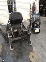
Then i burned er in
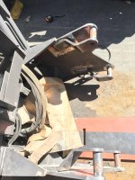
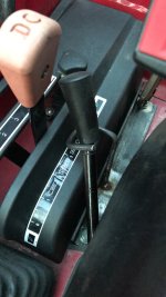
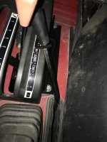
Last step, was my rear auxiliary control valve didn't have detents for postion A or B. So i made a little hook to slide the lever in to, to keep constant output in position A with the hoe hooked up.
Subframe all fitted to the tractor.
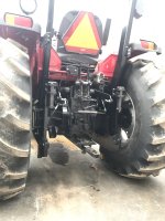
And here she is finished product
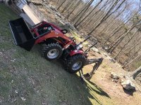
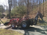
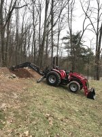
She works great and this setup is solid.
Total materials, including all steel plate and all new grade 8 hardware all around cost me under $100.
Maybe $20-40 in consumables like grinding discs, paint, etc.
Saved myself thousandssssss of dollars over new or buying the mounts from the factory.
It was a bit grueling at points working with such heavy material, and doing every single thing by myself, but it was worth it and i'm pretty happy with the finished product.
And check out my post on how i rebuilt the hydraulic control spool valve seals and check plug / relief port seals in the hydraulics section
http://www.tractorbynet.com/forums/hydraulics/393876-mahindra-75b-bradco-509-backhoe.html
Cheers.
-Haas
I recently purchased a left over 2016 Mahindra 3550 PST 4wd. I'm budget conservative, so did some searching for a used 75B / Bradco 509 backhoe attachement to go along with the tractor.
What do you know, I come across this used Bradco 509 that came off of a New Holland TN75 at a local used farm equipment lot. I got them down to $3000 cash, a solid score in my book after seeing other prices for used 509s, let alone a new one!
They said it had a few hydraulic leaks but was in good working order. Nothing I was too concerned about, so I went and picked er up.

Here is the bradco subrame for the New Holland that came with the hoe

My 3550 has factory subframe braces that tie the loader mount to the rear axle

And here is what I wanted to replicate/build; the setup bradco sold for my tractor

I did some serious research before hand, priced things out, before I decided this was the best route to go. I looked in to buying the subframe from the dealer, but that equated to several thousand dollars (which that cost is usually built in when you purchase the entire 75B setup).
I then looked in to buying the lower rear axle brackets to weld the NewHolland subframe to, so I didn't "destroy" my factory ones, or mess up and be SOL. Well the new axles bracket/plates cost $330 each from the dealer, and that was out the door quick.
So i decided to make my own from scratch. And to cut down the NewHolland subframe to my specs. And weld it all together.
I picked up two 10" x 10" x 0.75" thick plates for the axle plates, and two 12" x 12" x 0.50" thick plates for the 3-point arm brackets and bracing.
I tacked the 0.75" plates together, tacked the stock plate on top as a template, passed a drill bit down each hole to mark center, ground the tacks off for the stock plate, and went to town drilling these 5/8" holes. Cutting fluid is a must. This Harbor Freight drill press and slow speed drill bits work amazing and is one of the best budget pieces I've bought there. Don't get me wrong, I own Miller welders and other top equipment, but for the price of the HF press, it does one heck of a job for general fabrication. It has minimal run out but that's not critical in these applications.

One they were drilled, I ground off the tacks, traced the stock plate pattern and began to cut. I initally tried using the chinese 50amp plasma cutter we have (brother bought it while we were still in highschool years ago), and that wasn't having it and messed up one of my lines. So after that, I went to town with the dry cut metal chop saw where I could and the angle grinder with cut off wheel where I couldn't get. Man this was an ugly job, lotsssss of grinding. Wish I had a 100amp plasma table, haha (next year!)

Here you can see I already cut off the axle mount plate on the NewHolland subframe, cut it to the height i calculated, cut the ends off the length I needed (and accidentally measured from the wrong part, cutting on of them too short :laughing: which i had to weld a section back in then), cut a large v groove where the subframe was originally bent but i needed it straight (which i unbent by running it over with the tractors back tires and massage it the rest of the way with the 10lb sledge), and sat the factory plate on top as a mock up for what my plan was. The large bracket/mount that connects to the hoe is 1.25" thick, the rail running up to under the loader is 1" thick by 5". This wasn't fun work, haha, and the first time i've worked with greater than 0.25" for fabrication.

I then made cardboard templates of the 3point link tabs and traced them out to be cut with the plasma (which i found works ok after changing the tip and maxing the air pressure)

Rough cut straight after the hand plasma action

Pin holes drilled and tabs cleaned up, ready for welding

I drew a grid square to the bolt holes with options of where the subframe would weld to and tacked the tabs on

I bolted the new plates ontop of the factory plates to prevent warping during welding and burned them in, with all tabs beveled at the weld joint prior

I added on the bracing (some with extra material I had so it wasn't the prettiest) and then used these cool little 90* gussets I have from other chassis fab to keep the plate perfectly square on the subframe rail.

sat er on and tacked it in to place

then made the real bracing/gussets

tacked them on, knocked off the small temporary ones, and she was ready

burned er in hot (and in hindsight, probably could have bolted the factor plate on again to prevent warping, but didn't. only had slight warp post cooling which didn't effect fitment)

I then needed to fill in the giant notch i made where I removed the bend in the rails. I expected it to warp some, filling in that big with a lot of weld, but thought a few c-clamps and angle iron would do the trick.

Well after the initial root pass, she was bending on me pretty good and I knew it'd only get worse. So i remembered what a good friend told me to do when welding an axle truss on, chaining the axle on stands to a fab table and using a bottle jack in the center to bend it in the opposite direction. and post welding and cooling, when you relief the pressure, it'll end up straight.
So i rigged up this setup with 1/4" wall 2.5" x 2.5" square tub, inverted F350 superduty rotors that fit my jack stanks, gr70 chains, and a 10 ton bottle jack. Haha. I pretty much maxed the pressure of the jack with the little handle on it, and used an extension to get a little more pressure out of it. It bent the rail back past straight with a slight bow in it. I burned it, let it cool, and to my amazement... it was actually straight!

Next was to tie in the loader frame. Same deal, I cut 5"x7" plates; tacked them together; used the factory brace to pattern the holes and drilled them out. i made these so I could cut a 2" long by 1" high taper out of the rail and have it weld it flush. Gave it a little clearance and smooth transition if I happen to run in to anything. Plus that extra length wasn't really helping me since it was moderately past the frame backing.
Here they are tacked up.

And with that, they were ready for final welding and paint.

Now, before hand, I measured where the mounts normally come up behind the ROPs, and what that total width was. I then measured the backhoe side mounts and saw what I had to work with to minimize modification. I got lucky, and was able to plan my total tractor mount width to end up 0.25" inside the major plates of the backhoe side mounts. meaning I'd only have to grind the welds off of the stock backhoe side mount points, and flip them to the inside.
And here you can see I did that,
With the one side already removed, and the other side still in "stock" location

Again, a ton of grueling dirty grinder work.. on heavy material. it just sucks. But i'll make this note, i'm glad the welders bradco employs aren't great ones. because all of this stuff was welded too cold and too quick. There was no penetration/fusion in any of the weld joints. just the weld itself holding one piece to the other. I actually double taked several times when welding the tractor side subframe, seeing some of the factory welds and be like, wow, i really messed that one up and it looks like crappp, i should probably run another pass or two over it to tie it in better. only to lift my hood and be like oh, that's the factory one. haha but hey, they held just fine for the life of this hoe and clearly there aren't reports of bradco stuff falling apart. just something i wouldn't find acceptable for my own standards. Anyways.
So here i got er tacked up and made a final confirmation that measurements were ok

Then i burned er in

Last step, was my rear auxiliary control valve didn't have detents for postion A or B. So i made a little hook to slide the lever in to, to keep constant output in position A with the hoe hooked up.


Subframe all fitted to the tractor.

And here she is finished product


She works great and this setup is solid.
Total materials, including all steel plate and all new grade 8 hardware all around cost me under $100.
Maybe $20-40 in consumables like grinding discs, paint, etc.
Saved myself thousandssssss of dollars over new or buying the mounts from the factory.
It was a bit grueling at points working with such heavy material, and doing every single thing by myself, but it was worth it and i'm pretty happy with the finished product.
And check out my post on how i rebuilt the hydraulic control spool valve seals and check plug / relief port seals in the hydraulics section
http://www.tractorbynet.com/forums/hydraulics/393876-mahindra-75b-bradco-509-backhoe.html
Cheers.
-Haas
Last edited: