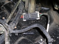
I can't tell the exact location by looking at the manual.
The technical manual says; "Test MFWD sensor. Check that MFWD is fully engaged. Check 502 Red wire and connections for short or open circuit."
It gives several pages of instructions on how to test the sensor using different methods. Plus electrical schematics. Following is the preferred method.
eHydro - MFWD Speed Sensor Test
Purpose:
The MFWD speed sensor is tested based upon the proper
voltage input and frequency output during a drive function.
The display panel (Diagnostic mode 2, preferred method)
or the test kit (JDG1575, optional method) or SERVICE
ADVISOR (optional method) can be used to test the
MFWD speed sensor.
Procedure - Diagnostic Mode 2:
Test Conditions:
Machine on jack stands.
Operator on seat.
Engine running with throttle at low idle.
Transmission in gear position A.
Park brake unlocked.
1. Verify engine speed is set within specification. See
Slow Idle Adjustment on page 54 in the Engine section.
2. Park machine safely and set to test conditions.
3. Enter the diagnostic mode 2. See Diagnostic Mode 2
(eHydro/Auto HST): on page 346.
4. Toggle the right turn signal switch to display position 11
(gSXXXX) for ground speed.
5. With the engine running at low idle and the range
transmission in gear position A, fully depress the forward
drive pedal and note the frequency reading on the display
panel. Move the throttle lever to the fast idle position and
note display reading.
6. Release the forward pedal, move the throttle lever to the
low idle position and shift the range transmission to gear
position B. Go to Step 5.
7. Release the forward pedal, move the throttle lever to the
low idle position and shift the range transmission to gear
position C. Go to Step 5.
8. If the frequency readings are not within specification,
MFWD Specification: on page 361), replace the
MFWD speed sensor..
Diagnostic Mode 2 (eHydro/Auto HST):
Note: The password is different for each access mode.
R = Right and L = Left on the turn signal switch.
1. Enter password, LRRRLR. Use this password to get the
information that is within the eHydro/Auto HST controller.
2. In this mode, Display controller communicates with the
eHydro controller to get the parameters as listed in the
following table.
Note: The diagnostic values are displayed live. The
values displayed will change (after refreshing the
display by cycling the display to the next higher or
lower address and then returning to the original
address) if the components for the item selected are
changed. Example, when the forward pedal voltage
(No. 17) is displayed, if the forward pedal is pressed,
the voltage reading on the display will also change
(after cycling).
3. Use left (B) or right (C) turn signal switch to navigate
through the parameters.
MFWD Specification:
Input Voltage . . . . . . . . . . . . . . . . . . . . . . . 5.0 ア 0.2 volts
Gear A - Frequency at Low Idle. . . . . . . . . 233 ア 0.1 kHz
Gear A - Frequency at High Idle . . . . . . . . 650 ア 2.0 kHz
Gear B - Frequency at Low Idle. . . . . . . . . 414 ア 0.1 kHz
Gear B - Frequency at High Idle . . . . . . . . 710 ア 2.0 kHz
Gear C - Frequency at Low Idle. . . . . . . . . 970 ア 0.1 kHz
Gear C - Frequency at High Idle . . . . . . . 2923 ア 2.0 kHz

