JCByrd24
Gold Member
Just finished up a recent project. My plow truck went in a divorce and I did the rear snowblower for 1 year after that. I liked the blower but hated going backwards and only having 3 rear speeds vs 9 forward, none were right in reverse. I started planning the front blower and found a John Deere 47" that would turn out to work very well. I toyed around with putting the rear one up front but the rotation was the wrong direction, was about 100lbs heavier (not good without power steering), and would stick out further due to the gearbox being behind the impeller instead of in the middle of the auger.
Please ignore the horrible paint job, too cold to spray so had to do it with a brush in the basement and potential snow was coming.
This is the overall product.
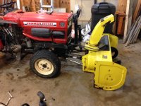
Closer look at the front end. The deere blower was not permanently modified. I unbolted the sprockets and associated bracket that reduce the roughly 2000rpm deere mid PTO to 950rpm impeller speed. I will run the blower with my 1000 RPM PTO speed. I made a bracket that uses existing holes in the blower to accept the upper link attachment (a weld on toplink ball). The other end of the upper link pivots on bushings I turned on the lathe. I wanted a semi-parallel linkage vs a simple pivot like deere does to avoid the need for a CV shaft. Deere has vibration issues when the blower is raised without their new CV shaft, as I learned on this site.
The hydraulic cylinder is powered from an accessory port that uses the 3PT circuit so I can raise and float the blower with the 3pt lift lever (3pt gets locked with needle valve). Bottom links are Cat 0 top links which at $9 were cheaper than making something, and the adjustable length allows me to quickly tilt the blower on the shoes to either scrape the pavement or raise the cutting edge up a little for the gravel part of the driveway.
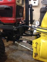
Here's the mounting bracket. Bolts to existing holes in the front bumper and a couple of tabs I welded onto the frame doubler plate that is added to Yanmars when an FEL is installed. The pivot rod on the top link is extra long because it came with the tractor and I'm not sure what it's for so I didn't want to cut it short and it doesn't bother anything being a bit long. PTO shaft is a series 1 spreader shaft. I changed out the 6-spline yoke to a 1" keyed/smooth to mate up to the blower.
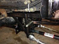
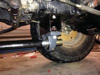
This is the front bearing mount. Attaches to existing 4 bolts that hold the axle pivot pin. A short length of 6-spline shafting for surplus center comes through the bearing to meet the PTO shaft. Just behind the bearing the shaft was turned down to a close fit inside a 1.5" DOM tube and welded to it. That's the first section of the driveshaft.
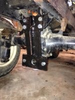
Here's the mid bearing. Lucked out here with 2 tapped holes in a perfectly flat surface in the bottom of the transmission housing. The front driveshaft ends just beyond this bearing with a female splined hub. The aft shaft is a short male splined section that slides into the front shaft and is welded to a u-joint yoke, the other yoke is welded to another section of DOM tube.
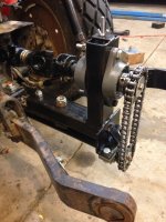
Here's the business end. The whole business is bolted to the drawbar, more on that below. You can see the aft driveshaft coming back to a pillow block bearing. The tube is welded to a 1" solid shaft. I cut the keyways on the lathe using a endmill held in a collet and shafts in a boring bar holder. Sprockets are from surplus center. Driven sprocket is 1 tooth less than driving, given me an extra few percent of RPM. In total I'm about 10% over JD spec. The upper bearings are mounted in slots for chain tensioning. The rod with the wing nut at the top is used to set the tension before tightening the bearing bolts. I drilled and tapped the ends of the shafts so I could add a bolt with a large washer as a backup for the set-screws holding everything together. The PTO shaft is another series 1 but in this case the yokes are back to back with no length change possible. The outer tube was cut flush with the yoke and the inner tube is just long enough to match the outer within the yoke. The roll pin on the outer yoke goes through both tubes. I removed the QD pin from the rear yoke so there is play lengthwise at the rear splined joint if necessary.
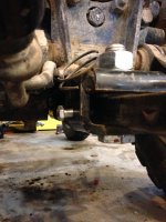
The drawbar was modified with some fine thread bolts to hold it's location tight laterally, and a 7/8" washer tapped right in snug to make it tight vertically as well. This prevents noise/rattling and misalignment of the sprockets, though there is enough play that this step may not have been necessary.
The chute rotation is stock hydraulic Deere with appropriate QDCs for my loader valve. I'm going to modify that soon for a little more travel as is commonly done. I also have a linear actuator for the chute deflector. Could have done hydraulic but this was cheaper and less likely to break the plastic hinge on the deflector. Finally I need to pull the augers and impeller and balance them. My driveshaft runs beautifully at 1000RPM but the impeller vibrates some and the augers rock the unit side to side. Another common issue. I will post on that separately.
Oh and I have a piece of 2" plate about 14" x 14" that will become a counterweight/chain guard so I don't back into something with the chain. It'll be 3pt mounted and just clear the chain drive. I don't have kids or pets that tend to play around the tractor so I'm not sure I will do a true chain guard, but we'll see.
Please ignore the horrible paint job, too cold to spray so had to do it with a brush in the basement and potential snow was coming.
This is the overall product.

Closer look at the front end. The deere blower was not permanently modified. I unbolted the sprockets and associated bracket that reduce the roughly 2000rpm deere mid PTO to 950rpm impeller speed. I will run the blower with my 1000 RPM PTO speed. I made a bracket that uses existing holes in the blower to accept the upper link attachment (a weld on toplink ball). The other end of the upper link pivots on bushings I turned on the lathe. I wanted a semi-parallel linkage vs a simple pivot like deere does to avoid the need for a CV shaft. Deere has vibration issues when the blower is raised without their new CV shaft, as I learned on this site.
The hydraulic cylinder is powered from an accessory port that uses the 3PT circuit so I can raise and float the blower with the 3pt lift lever (3pt gets locked with needle valve). Bottom links are Cat 0 top links which at $9 were cheaper than making something, and the adjustable length allows me to quickly tilt the blower on the shoes to either scrape the pavement or raise the cutting edge up a little for the gravel part of the driveway.

Here's the mounting bracket. Bolts to existing holes in the front bumper and a couple of tabs I welded onto the frame doubler plate that is added to Yanmars when an FEL is installed. The pivot rod on the top link is extra long because it came with the tractor and I'm not sure what it's for so I didn't want to cut it short and it doesn't bother anything being a bit long. PTO shaft is a series 1 spreader shaft. I changed out the 6-spline yoke to a 1" keyed/smooth to mate up to the blower.

This is the front bearing mount. Attaches to existing 4 bolts that hold the axle pivot pin. A short length of 6-spline shafting for surplus center comes through the bearing to meet the PTO shaft. Just behind the bearing the shaft was turned down to a close fit inside a 1.5" DOM tube and welded to it. That's the first section of the driveshaft.

Here's the mid bearing. Lucked out here with 2 tapped holes in a perfectly flat surface in the bottom of the transmission housing. The front driveshaft ends just beyond this bearing with a female splined hub. The aft shaft is a short male splined section that slides into the front shaft and is welded to a u-joint yoke, the other yoke is welded to another section of DOM tube.

Here's the business end. The whole business is bolted to the drawbar, more on that below. You can see the aft driveshaft coming back to a pillow block bearing. The tube is welded to a 1" solid shaft. I cut the keyways on the lathe using a endmill held in a collet and shafts in a boring bar holder. Sprockets are from surplus center. Driven sprocket is 1 tooth less than driving, given me an extra few percent of RPM. In total I'm about 10% over JD spec. The upper bearings are mounted in slots for chain tensioning. The rod with the wing nut at the top is used to set the tension before tightening the bearing bolts. I drilled and tapped the ends of the shafts so I could add a bolt with a large washer as a backup for the set-screws holding everything together. The PTO shaft is another series 1 but in this case the yokes are back to back with no length change possible. The outer tube was cut flush with the yoke and the inner tube is just long enough to match the outer within the yoke. The roll pin on the outer yoke goes through both tubes. I removed the QD pin from the rear yoke so there is play lengthwise at the rear splined joint if necessary.

The drawbar was modified with some fine thread bolts to hold it's location tight laterally, and a 7/8" washer tapped right in snug to make it tight vertically as well. This prevents noise/rattling and misalignment of the sprockets, though there is enough play that this step may not have been necessary.

The chute rotation is stock hydraulic Deere with appropriate QDCs for my loader valve. I'm going to modify that soon for a little more travel as is commonly done. I also have a linear actuator for the chute deflector. Could have done hydraulic but this was cheaper and less likely to break the plastic hinge on the deflector. Finally I need to pull the augers and impeller and balance them. My driveshaft runs beautifully at 1000RPM but the impeller vibrates some and the augers rock the unit side to side. Another common issue. I will post on that separately.
Oh and I have a piece of 2" plate about 14" x 14" that will become a counterweight/chain guard so I don't back into something with the chain. It'll be 3pt mounted and just clear the chain drive. I don't have kids or pets that tend to play around the tractor so I'm not sure I will do a true chain guard, but we'll see.
Last edited: