I recently added a hydraulically adjustable 4 way wedge to my home built wood splitter. I bought the splitter many years ago for around $200.00 and over the years I have replaced everything but the I beam, basic chassis, and the oil tank. I added a 13 HP HF engine, high flow pump, auto return valve, and a log loader.
I bought the hydraulics and I have access to the drops at a friend's steel fabrication shop. I think I'm all in for right around $250.00 for this project.
The wedge is 1" plate, the brace behind the wedge is 1/2" plate and the actuator is made from 3/8 plate. I cut the 1/2 and 3/8 using a Milwaukee steel cutting circular saw. The rough vertical cuts on the 1" were made with a torch and cleaned up with a cut off wheel.
I was looking at adding a box wedge, but after doing some research I wasn't sold on it so I decided to add a the adjustable wedge instead. I had three concerns as I researched the idea; what were the measurements for the actuating mechanism?, how could I cut the slot at the bottom of the wedge?, and how could I get a sharpened edge on the wedge?
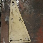
I looked for the measurements on-line without success, although I'm sure they are out there somewhere, so I ended up freezing a video of an adjustable wedge which allowed me to use dividers to measure the one known given dimension of the hydraulic ram. In turn I used that measurement to figure out the distance between the holes on the actuator and with a little math I came up with what I figured would be a good starting point. I then mocked up the actuator using MDF and plywood and much to my surprise the dimensions worked. The dimensions are in the picture below. As the saying goes "Past performance is no guarantee of future success.", but here is what I used.
Point "A" is where the pin goes through the slot at the bottom of the wedge, "B" is where the hydraulic cylinder connects, and "C" is where the actuator connects to the bracket mounted on the bottom of the beam. A to B is 13 1/2", B to C is 6", and A to C is 12" (All dimensions center to center). The bracket is 7 5/8" from the beam bottom to the hole center. The distance from "B" to the mount for the cylinder will vary with each cylinder, but you want the pin in the wedge slot to be about 1 1/2" from the front edge of the slot with the piston fully retracted and the wedge at the full up position. This in turn sets where the bracket gets mounted. The wedge was 5" wide before sharpening and the slot is 3 3/4" wide.
I was able to cut the slot by drilling holes in each end of the slot and than connecting them with a 4 1/2" cut off disc. A little filing and it worked. I initially made the slot 5/8" diameter, but that proved too tight, so I widened it to 3/4".
The wedge 5" x 30"x 1"with a 12" vertical range of motion. The horizontal wedges are mounted 12" above the beam resulting in the ability to cut a 24" log into quarters and was cut from 1" thick stock by a friend who is much better than I ever was or will be at using a torch. I then finished them using a 4 1/2" grinder equipped with 36 grit sanding discs. I filled any deep slots with weld to speed up the process, but it still took several hours of grinding. The vertical wedge is ground to a "V" and the horizontal wedge is a flat bevel to prevent the wood from binding under it. This also allows wood to slide up over it with the wedge in the lowest position.
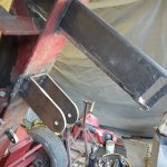
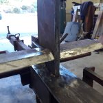
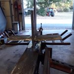
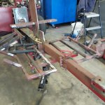
Overall I'm pleased with they way it came out, but I made a couple of mistakes that needed fixing. The big boo-boo I made was initially cutting the slot in the beam that the wedge rides through too long. This resulted in allowing the wedge to move front to back and put all of the force on the brace behind the wedge which failed from that and the improper weld from using too cold a setting to weld it initially. I ended up cutting a "Dutchman" in the top of the beam and welding it in to close the gap up. I also added plate to the beam bottom positioned against the wedge to hold it in alignment. Once I re-welded the brace properly the wedge does not move under full pressure. My advice is to cut that slot a precisely as you can so the wedge just fits length wise.


