leonz
Super Member
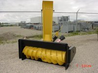
The market needs a new single stage snow thrower with either a smaller outside diameter snow thrower rotor
or a snow thrower rotor with 3" tall flighting around a larger diameter tube weldment with 15 degree auger flights
and 6 center paddles spaced 60 degrees apart.
The snow blower rotor could spin up to 900 revolutions per minute with the correct sprockets and a speed increaser
with enough torque operate at a very high output per hour as the larger diameter snow blower rotor tube will
encounter less resistance in snow loading as it advances into the snowpack to clear it.
The new snow blower should have 2 row 80H roller chain and sprockets to provide the desired torque for the
snow thrower to cast snow at a greater distance.
Why the 2 row 80H roller chain and sprockets?
The 2 row 80H roller chain and sprockets will provide the desired torque to spin the snow thrower rotor at a
high speed to clear snowpack.
The 2 row 80H roller chain and the 2 row 80H sprockets are heavier and will withstand greater shock loading
from clearing snowpack.
The 540 RPM right angle gear box, 1 to 1.6 speed increaser, cross shaft and flange roller bearing supporting
the cross shaft are simple off the shelf parts.
The 1 to 1.6 speed increaser would be mounted to the snow thrower lifting frame as it would be mounted on a
vertical steel plate welded to the lifting frame of the 3 point hitch to the left of the right angle gearbox.
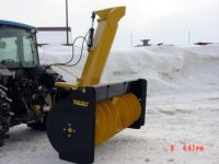
The snow blower rotor could be equipped with 2 sets of casting paddles and 2 simple plate steel chutes to
increase its casting capacity per minute.
The chute or chutes would be mounted on a slick sheet material to allow the chute or chutes to spin effortlessly
with a manual rotator or a double acting hydraulic cylinder bolted to a weldment on the snow throwers curved shell
The chute or chutes would have slick sheet material bolted to the chute or chutes with grain elevator bolts flat washers
and nylock nuts.
The length of the single or dual linkages that rotate the chute or chutes would have to be decided when the
design is finalized as the user would want 180 degrees of chute rotation to discharge the snow left or right
and it would require an arc of throw to spin the chute or chutes left or right with the cylinder rod extended
for discharge to the right of center or retracted for discharge to the left of center.
Thoughts on a lousy looking day.
or a snow thrower rotor with 3" tall flighting around a larger diameter tube weldment with 15 degree auger flights
and 6 center paddles spaced 60 degrees apart.
The snow blower rotor could spin up to 900 revolutions per minute with the correct sprockets and a speed increaser
with enough torque operate at a very high output per hour as the larger diameter snow blower rotor tube will
encounter less resistance in snow loading as it advances into the snowpack to clear it.
The new snow blower should have 2 row 80H roller chain and sprockets to provide the desired torque for the
snow thrower to cast snow at a greater distance.
Why the 2 row 80H roller chain and sprockets?
The 2 row 80H roller chain and sprockets will provide the desired torque to spin the snow thrower rotor at a
high speed to clear snowpack.
The 2 row 80H roller chain and the 2 row 80H sprockets are heavier and will withstand greater shock loading
from clearing snowpack.
The 540 RPM right angle gear box, 1 to 1.6 speed increaser, cross shaft and flange roller bearing supporting
the cross shaft are simple off the shelf parts.
The 1 to 1.6 speed increaser would be mounted to the snow thrower lifting frame as it would be mounted on a
vertical steel plate welded to the lifting frame of the 3 point hitch to the left of the right angle gearbox.
The snow blower rotor could be equipped with 2 sets of casting paddles and 2 simple plate steel chutes to
increase its casting capacity per minute.
The chute or chutes would be mounted on a slick sheet material to allow the chute or chutes to spin effortlessly
with a manual rotator or a double acting hydraulic cylinder bolted to a weldment on the snow throwers curved shell
The chute or chutes would have slick sheet material bolted to the chute or chutes with grain elevator bolts flat washers
and nylock nuts.
The length of the single or dual linkages that rotate the chute or chutes would have to be decided when the
design is finalized as the user would want 180 degrees of chute rotation to discharge the snow left or right
and it would require an arc of throw to spin the chute or chutes left or right with the cylinder rod extended
for discharge to the right of center or retracted for discharge to the left of center.
Thoughts on a lousy looking day.