You are using an out of date browser. It may not display this or other websites correctly.
You should upgrade or use an alternative browser.
You should upgrade or use an alternative browser.
4320 Coolant Leak from Timing Cover advise please
- Thread starter gbw
- Start date
/ 4320 Coolant Leak from Timing Cover advise please
#21
brad5541
New member
- Joined
- Mar 21, 2023
- Messages
- 7
- Tractor
- 4520 hydro
Thanks bud. I'm a mechanic/equipment manager at a golf course . We use this tractor for pulling a rough mower. TractoR Has about 4000 hours and gets used every day in the summer. Thanks for pictures of instructions that will help. Currently waiting on the bushings for the front trunion and oil pan trunion. What's the best way to get those bushings out? I was thinking I could cut them hopefully. Thanks for all your helpLooks like you have a nice shop there. How many hrs on the tractor? The reason I ask is the front tires look worn out. The only thing I was hesitant about when I reinstalled the FEC was getting the governor linkage aligned correctly. The writeup calls to use two alignment pins/ bolts? to align the FEC. I had extra bolts because the kit contains new. I cut the heads off and and used them as alignment pins, at 2 places opposite each other around the crank bore area.
oldtimer 66
Gold Member
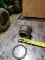
I cut them out part way then chiseled and pryed and or I used a ball burr bit. I am have trouble remembering. They are tricky to put in. The OD is smooth from the laminations applied to the die, the ID is rough. When I said they were reinforced nylon 66 that was wrong. They must be some type of reinforced fiberglass/ urethane mixture molded in a sleeve. I took some emery and hand dressed the od's of the trunnion spindles because of the wavy surface. I might have lightly hand filed the surfaces also. My tractor only had 1000 hrs when I did this repair. Your tractor has 4000 hrs so I imagine those trunnion spindles will be much more wavy. I put the trunnion assembly together dry. If you put in lubrication/ grease that will only attract dirt and debris and wear the bushings trunnion spindles faster. The picture shows what I used to install the large oil pan bushing. It is a 2.0 pipe union, just the male part. I couldn't get the pipe out so I just cut it off. The 2.0" male union fit the large oil pan bushing and the its lip fit the end of the bushing perfectly. A work of caution, I tried to install the large bushing without the male union and I destroyed the first bushing. I froze the bushing but it only went in half way and by that time the end of the bushing was mushroomed/ fibers everywhere from just tapping lightly on the end. So I used the male union part with the second bushing and I put both of them together in the freezer/ refrigerator type over night. No problem the next day but you need to work fast. I don't have the picture, let's call it a tool , for the smaller bushing. I don't remember exactly what I used to install that bushing but the process was the same. Tool and bushing together in the freezer. I think I saw a lathe at your shop. It may come in handy to make one or both of these tools and or get a 2.0" pipe union for one of the tools. The picture shows the original large thrust washer. Dims. Thk. X 2.25" ID X 2.90" OD. At the JD dealer there were several thrust washer part numbers listed and they were all different, but I purchased them all. I don't remember which ones I used. What surprised me was the pricing of these bushings. Relatively cheap at that time, $10/$11 for a John Deere part. Un heard of today. If the thrust washer OD is larger than the ID of the bushing make sure you install the thrust washer first. Measure the length of the bushings and don't drive them deep into the hole. You want the bushings to cover as much of the trunnion spindles as possible. Don't forget the steel washer/ lateral adjustment/ behind the thrust washer on the small trunnion spindle. Have at it.


brad5541
New member
- Joined
- Mar 21, 2023
- Messages
- 7
- Tractor
- 4520 hydro
I cut them out part way then chiseled and pryed and or I used a ball burr bit. I am have trouble remembering. They are tricky to put in. The OD is smooth from the laminations applied to the die, the ID is rough. When I said they were reinforced nylon 66 that was wrong. They must be some type of reinforced fiberglass/ urethane mixture molded in a sleeve. I took some emery and hand dressed the od's of the trunnion spindles because of the wavy surface. I might have lightly hand filed the surfaces also. My tractor only had 1000 hrs when I did this repair. Your tractor has 4000 hrs so I imagine those trunnion spindles will be much more wavy. I put the trunnion assembly together dry. If you put in lubrication/ grease that will only attract dirt and debris and wear the bushings trunnion spindles faster. The picture shows what I used to install the large oil pan bushing. It is a 2.0 pipe union, just the male part. I couldn't get the pipe out so I just cut it off. The 2.0" male union fit the large oil pan bushing and the its lip fit the end of the bushing perfectly. A work of caution, I tried to install the large bushing without the male union and I destroyed the first bushing. I froze the bushing but it only went in half way and by that time the end of the bushing was mushroomed/ fibers everywhere from just tapping lightly on the end. So I used the male union part with the second bushing and I put both of them together in the freezer/ refrigerator type over night. No problem the next day but you need to work fast. I don't have the picture, let's call it a tool , for the smaller bushing. I don't remember exactly what I used to install that bushing but the process was the same. Tool and bushing together in the freezer. I think I saw a lathe at your shop. It may come in handy to make one or both of these tools and or get a 2.0" pipe union for one of the tools. The picture shows the original large thrust washer. Dims. Thk. X 2.25" ID X 2.90" OD. At the JD dealer there were several thrust washer part numbers listed and they were all different, but I purchased them all. I don't remember which ones I used. What surprised me was the pricing of these bushings. Relatively cheap at that time, $10/$11 for a John Deere part. Un heard of today. If the thrust washer OD is larger than the ID of the bushing make sure you install the thrust washer first. Measure the length of the bushings and don't drive them deep into the hole. You want the bushings to cover as much of the trunnion spindles as possible. Don't forget the steel washer/ lateral adjustment/ behind the thrust washer on the small trunnion spindle. Have at it.
View attachment 790418
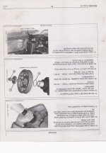
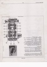
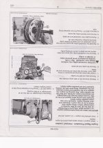
Thanks for all your help. I printed out the instructions today. What's funny is I actually called the john deere dealer asking about these instructions and they had no clue and couldn't find it. I would've thought should've came with the engine gasket kit. Also the kit I got didn't come with new oil pan bolts like it states in the instructions. I have about 20 bolts left in the kit that i have no clue whete they go. I'm guessing there for a different oil pan and not the cast iron pan that i have. I spent about a hour or more getting the old trunnion bushings out and had fiberglass everywhere. Hopefully the new bushings will be here Monday just have to find a union like you got to install.I cut them out part way then chiseled and pryed and or I used a ball burr bit. I am have trouble remembering. They are tricky to put in. The OD is smooth from the laminations applied to the die, the ID is rough. When I said they were reinforced nylon 66 that was wrong. They must be some type of reinforced fiberglass/ urethane mixture molded in a sleeve. I took some emery and hand dressed the od's of the trunnion spindles because of the wavy surface. I might have lightly hand filed the surfaces also. My tractor only had 1000 hrs when I did this repair. Your tractor has 4000 hrs so I imagine those trunnion spindles will be much more wavy. I put the trunnion assembly together dry. If you put in lubrication/ grease that will only attract dirt and debris and wear the bushings trunnion spindles faster. The picture shows what I used to install the large oil pan bushing. It is a 2.0 pipe union, just the male part. I couldn't get the pipe out so I just cut it off. The 2.0" male union fit the large oil pan bushing and the its lip fit the end of the bushing perfectly. A work of caution, I tried to install the large bushing without the male union and I destroyed the first bushing. I froze the bushing but it only went in half way and by that time the end of the bushing was mushroomed/ fibers everywhere from just tapping lightly on the end. So I used the male union part with the second bushing and I put both of them together in the freezer/ refrigerator type over night. No problem the next day but you need to work fast. I don't have the picture, let's call it a tool , for the smaller bushing. I don't remember exactly what I used to install that bushing but the process was the same. Tool and bushing together in the freezer. I think I saw a lathe at your shop. It may come in handy to make one or both of these tools and or get a 2.0" pipe union for one of the tools. The picture shows the original large thrust washer. Dims. Thk. X 2.25" ID X 2.90" OD. At the JD dealer there were several thrust washer part numbers listed and they were all different, but I purchased them all. I don't remember which ones I used. What surprised me was the pricing of these bushings. Relatively cheap at that time, $10/$11 for a John Deere part. Un heard of today. If the thrust washer OD is larger than the ID of the bushing make sure you install the thrust washer first. Measure the length of the bushings and don't drive them deep into the hole. You want the bushings to cover as much of the trunnion spindles as possible. Don't forget the steel washer/ lateral adjustment/ behind the thrust washer on the small trunnion spindle. Have at it.
View attachment 790418
brad5541
New member
- Joined
- Mar 21, 2023
- Messages
- 7
- Tractor
- 4520 hydro
Im little confused about measuring for the Lshaped gasket and shim calculating the gap. Says to bolt cover without gasket and measure through fan mount. So Im guessing if the gap is more 2.85mm the shim needs installed? It also has a minimum 1.85mm. Thinking I'm just going leave that shim outI cut them out part way then chiseled and pryed and or I used a ball burr bit. I am have trouble remembering. They are tricky to put in. The OD is smooth from the laminations applied to the die, the ID is rough. When I said they were reinforced nylon 66 that was wrong. They must be some type of reinforced fiberglass/ urethane mixture molded in a sleeve. I took some emery and hand dressed the od's of the trunnion spindles because of the wavy surface. I might have lightly hand filed the surfaces also. My tractor only had 1000 hrs when I did this repair. Your tractor has 4000 hrs so I imagine those trunnion spindles will be much more wavy. I put the trunnion assembly together dry. If you put in lubrication/ grease that will only attract dirt and debris and wear the bushings trunnion spindles faster. The picture shows what I used to install the large oil pan bushing. It is a 2.0 pipe union, just the male part. I couldn't get the pipe out so I just cut it off. The 2.0" male union fit the large oil pan bushing and the its lip fit the end of the bushing perfectly. A work of caution, I tried to install the large bushing without the male union and I destroyed the first bushing. I froze the bushing but it only went in half way and by that time the end of the bushing was mushroomed/ fibers everywhere from just tapping lightly on the end. So I used the male union part with the second bushing and I put both of them together in the freezer/ refrigerator type over night. No problem the next day but you need to work fast. I don't have the picture, let's call it a tool , for the smaller bushing. I don't remember exactly what I used to install that bushing but the process was the same. Tool and bushing together in the freezer. I think I saw a lathe at your shop. It may come in handy to make one or both of these tools and or get a 2.0" pipe union for one of the tools. The picture shows the original large thrust washer. Dims. Thk. X 2.25" ID X 2.90" OD. At the JD dealer there were several thrust washer part numbers listed and they were all different, but I purchased them all. I don't remember which ones I used. What surprised me was the pricing of these bushings. Relatively cheap at that time, $10/$11 for a John Deere part. Un heard of today. If the thrust washer OD is larger than the ID of the bushing make sure you install the thrust washer first. Measure the length of the bushings and don't drive them deep into the hole. You want the bushings to cover as much of the trunnion spindles as possible. Don't forget the steel washer/ lateral adjustment/ behind the thrust washer on the small trunnion spindle. Have at it.
View attachment 790418
oldtimer 66
Gold Member
Brad 5541 yes leave the shim out. The factory dimension has not changed. Besides they have you measuring over a cast surface which is radiused. Depending what you are using, dial caliper, depth mic you could get just about any reading each time you measured it. That is the reason I called it a mickey mouse measurement. I could see using the shim if the surface around the opening is eroded from coolant and then I would use it. Other than that no, because it just adds another surface to leak. A previous picture showed the kit. You need to use the new FEC bolts, the 11 count and the 6 count, because there are a torque turn bolt as the instructions call out. You can reuse the oil pan bolts because they are not torque turn hardware. It could be they changed the parts list on the kit and or you have a different kit without the oil pan bolts. If you look at the date on the instruction it is either from 2010 and or 2012. There could be several changes since then.
oldtimer 66
Gold Member
I just remembered, the oil pan bolts in the kit are for the stamped steel oil pan. The engine has other application where the cast oil pan is not required/ no spindle support.
brad5541
New member
- Joined
- Mar 21, 2023
- Messages
- 7
- Tractor
- 4520 hydro
Thanks. Hopefully by today I will have this thing back together. I will keep you updated. Thanks for all your help.I just remembered, the oil pan bolts in the kit are for the stamped steel oil pan. The engine has other application where the cast oil pan is not required/ no spindle support.
GBW and Brad5541, I wanted to get some more pictures to you. The problem area on the forward end cover that leaked was around the road course formed gasket near the water inlet. This gasket is the connection between the FEC and the cylinder head and that is where JD has you do some mickey mouse measuring and apply the brass shim. I think when my tractor was still under warranty the dealer replaced the upper radiator hose 2 times thinking that this was the problem. That is not the problem unless you have coolant erosion now on the cylinder head in the sealing area. The factory dimension are still valid. The major problem with this design is that they made the FEC out of aluminum and the engine block and cylinder head out of cast iron. On a temperature cycle the is a difference of about .020" plus that frets this connection between the FEC and the cylinder head causing the leak. I think it also erodes the other sealing surfaces at the water pump internally and around the oil pump area internally. Notice the rough as cast surface and JD expected this surface to seal with there mickey mouse formed nitrile? gasket. The groove is rough cast along with the eyebrow along the inside and outside of the groove. This area should have been machined at the factory. To remedy this finish problem I hand filed this eyebrow area smooth around the groove. I did not use a speed lock disk and or any power tool. I just wanted to keep the area flat with a good finish. This hand filing needs to be done but just to clean up with minimum metal removed. I think one of the pictures shows this surface after filing but I am not sure and I don't remember taking a finish picture of this area only the as cast surface. I am still going to look for that alignment tool but I don't think I ordered it. Also depending upon how you disconnected the throttle you may need to access the ECM to reset the engine idle. Its set according to voltage/ like .5 to .7 volts. But if you need that info I think I can send it.
View attachment 790027View attachment 790028View attachment 790029View attachment 790030View attachment 790031View attachment 790032
So I have a 2009 4320 with the same coolant leak. Does the John Deere tech manual adequately cover the procedure to disassemble the tractor to fix the leak.GBW and Brad5541, I wanted to get some more pictures to you. The problem area on the forward end cover that leaked was around the road course formed gasket near the water inlet. This gasket is the connection between the FEC and the cylinder head and that is where JD has you do some mickey mouse measuring and apply the brass shim. I think when my tractor was still under warranty the dealer replaced the upper radiator hose 2 times thinking that this was the problem. That is not the problem unless you have coolant erosion now on the cylinder head in the sealing area. The factory dimension are still valid. The major problem with this design is that they made the FEC out of aluminum and the engine block and cylinder head out of cast iron. On a temperature cycle the is a difference of about .020" plus that frets this connection between the FEC and the cylinder head causing the leak. I think it also erodes the other sealing surfaces at the water pump internally and around the oil pump area internally. Notice the rough as cast surface and JD expected this surface to seal with there mickey mouse formed nitrile? gasket. The groove is rough cast along with the eyebrow along the inside and outside of the groove. This area should have been machined at the factory. To remedy this finish problem I hand filed this eyebrow area smooth around the groove. I did not use a speed lock disk and or any power tool. I just wanted to keep the area flat with a good finish. This hand filing needs to be done but just to clean up with minimum metal removed. I think one of the pictures shows this surface after filing but I am not sure and I don't remember taking a finish picture of this area only the as cast surface. I am still going to look for that alignment tool but I don't think I ordered it. Also depending upon how you disconnected the throttle you may need to access the ECM to reset the engine idle. Its set according to voltage/ like .5 to .7 volts. But if you need that info I think I can send it.
View attachment 790027View attachment 790028View attachment 790029View attachment 790030View attachment 790031View attachment 790032


