2320 Pto shaft is bogging down / slipping !!

   / 2320 Pto shaft is bogging down / slipping !! #21  
Orifice might be in the priority flow control valve. I suspect pressure tap would be down stream of the orifice but that is just a semi educated guess. Does the service manual show the valves in exploded views or just talk about them. If that orifice is partially plugged the flow would go to the charge circuit.
 
   / 2320 Pto shaft is bogging down / slipping !!
  • Thread Starter
#22  
I can’t find any specific images or home for the priority flow control valve. I’ve attached blow up of the hydraulic pump with senenoid. There is control valve below the rock shaft housing (and next page top the number descriptions).
 

Attachments

  • CB59FC34-717F-4F83-8FE1-F4987BB0D376.png
    CB59FC34-717F-4F83-8FE1-F4987BB0D376.png
    823.7 KB · Views: 73
  • A113607A-2058-4B16-AE8C-D1998D0AE452.png
    A113607A-2058-4B16-AE8C-D1998D0AE452.png
    773.7 KB · Views: 73
  • 66D370BE-866F-4B59-BBB7-A301065F4E8F.jpeg
    66D370BE-866F-4B59-BBB7-A301065F4E8F.jpeg
    719.2 KB · Views: 81
   / 2320 Pto shaft is bogging down / slipping !! #23  
I agree that the priority flow control does appear to be in that housing. Per the schematic there is a double pump on your tractor. One section is for steering and implements the other is charge PTO and brake circuit. Is there anything in the hydraulic section showing lines, filter location etc. Per the schematic the line goes from pump to filter and then to priority valve. I suspect the filter is on the transaxle so possibly priority valve is in same area of transaxle. Sorry not much help on where this valve is.
 
   / 2320 Pto shaft is bogging down / slipping !!
  • Thread Starter
#24  
The strainer is in the lower rear of transaxle. The filter is visible on the attached. Seems on schematic the drive shaft powers hydrostat separately and there is side gear to power charge pump ( although don’t see that “pump”) which feeds the hydraulic motor. I see where the lines circulate to filter. And see now that the hydraulic motor splits one line to rock shaft and other the pto circuit. But I can’t see where the line or passage is that is opened when senenoid opens. It’s a mystery on diagram. I guess directly below or to side given it’s location on transaxle just above pto clutch.
I also don’t see where strainer fits in as it’s quite far and isolated from these lines. I will add more schematics just in case. And you’re very helpful. This is opening up a lot of knowledge for me.
 

Attachments

  • 778C87C8-445A-4A3A-8F27-10F3771EFAE8.png
    778C87C8-445A-4A3A-8F27-10F3771EFAE8.png
    1.1 MB · Views: 76
  • E5579F01-BF60-4AA4-AD07-5E89A52C347C.png
    E5579F01-BF60-4AA4-AD07-5E89A52C347C.png
    702.9 KB · Views: 74
   / 2320 Pto shaft is bogging down / slipping !! #25  
Is there another pump somewhere dedicated to charge circuit? It could be part of the hydrostatic pump assembly. I suspect yes but again not sure. I believe what you have posted is the main pump for steering and implements. I believe that is a totally seperate circuit.
 
   / 2320 Pto shaft is bogging down / slipping !!
  • Thread Starter
#26  
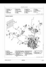
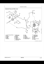
I’ve attached a helpful (to me) operation page. It seems the charge pump is in centre block and feeds oil at lowish 100psi to all. The hydrostat creates really strong pressure for drive (only) in either direction. The hydraulic pump gets oil from charge pump but does actually seem to only feed steering and implements/draft arms. So you seem to already have that figured out. And the pto circuit gets oil from the charge pump through the flow control valve. So yes ….it is separate it seems. I need to find the flow control valve and orifice. It’s a mystery. And in that area there must be a test port.

How does the oil actually compress pto clutch ? In the disassembly pics of centre case gears, bearings, shafts and clutch plates….it’s all open to case. I don’t understand how or what drives the plates together. Is the oil actuating a mechanical arm? In any case I should check charge pressure as first step. And inspect and clean screen.
 

Attachments

  • CD2C32A6-E8CC-4736-A0AF-BE2CB96C5820.png
    CD2C32A6-E8CC-4736-A0AF-BE2CB96C5820.png
    1.4 MB · Views: 61
   / 2320 Pto shaft is bogging down / slipping !! #27  
I looked at Deere parts diagram today and they were vague but it almost looked like some extra valves in the hydrostatic motor base plate. Even had one item labeled pump but that looked mislabeled to me. I could find no parts breakdown for the HST pump assembly though or reference to another filter. This sure is a puzzler.
 
   / 2320 Pto shaft is bogging down / slipping !! #28  
Looks like we posted at same time. Charge pressure would not show PTO pressure but test ports could be in same general area. The saga continues.
 
   / 2320 Pto shaft is bogging down / slipping !!
  • Thread Starter
#29  
Haha yes.
I’ve have the hydrostatic down to individual parts several times (two broken output shafts thanks to siezed drive shaft u joints. There is nothing really there other than check valves. I suspect one of the valves on the centre block (charge pump) might be involved and is close to the clutch. The selenoid is right next to that upper right area.
Does an orifice alone bring 100psi up to 310 for pto without added pump ?

Sorry for all the questions and many many Thanks for all your effort!. I will ask the dealer if they have any secret insight.
 
   / 2320 Pto shaft is bogging down / slipping !! #30  
Does an orifice alone bring 100psi up to 310 for pto without added pump ?

Sorry for all the questions and many many Thanks for all your effort!. I will ask the dealer if they have any secret insight.
No the orifice (flow control) just limits the flow going to the PTO circuit the relief valve in the PTO circuit controls the pressure.

No problem on questions and I hope some of my answers are helpful. Good luck at the dealer. They should have specs on procedure to check PTO pressure.
 
 
Top